Site Plan for Permit: 9 Items Reviewers Check First
Oleh Onysko 16 October 2026 13 min read
In this article
A site plan for permit is one scaled sheet that shows your lot lines, the existing buildings and the proposed work, with measured distances from that work to each relevant boundary. Build it on a boundary record your permit office accepts, label every offset, and then compare those offsets with the local setback rules.
Here is the part most people get backwards: drafting quality is rarely what stalls a review. A clean CAD drawing on top of a parcel map screenshot is weaker than a hand sketch on top of a recorded survey, because the reviewer is judging the facts underneath the lines. And a measured offset on your sheet is evidence of geometry, not a ruling. "10 ft to the left boundary" tells the reviewer where the deck sits. Whether 10 ft is enough is their call.
| Site plan fact | What it means for you |
|---|---|
| Base drawing | Survey or recorded plat the office accepts, with its date |
| Core content | Lot lines, existing and proposed work, offsets, scale, north arrow |
| Offsets vs setbacks | Show measured offsets; list required setbacks separately |
| Area labels | Footprint, floor area and coverage are different numbers |
| Who decides | Your permit office sets the checklist and the rules |
| Worked example | 16 x 12 ft deck, 192 sq ft, on a 60 x 100 ft lot |
What a plot plan for permit shows
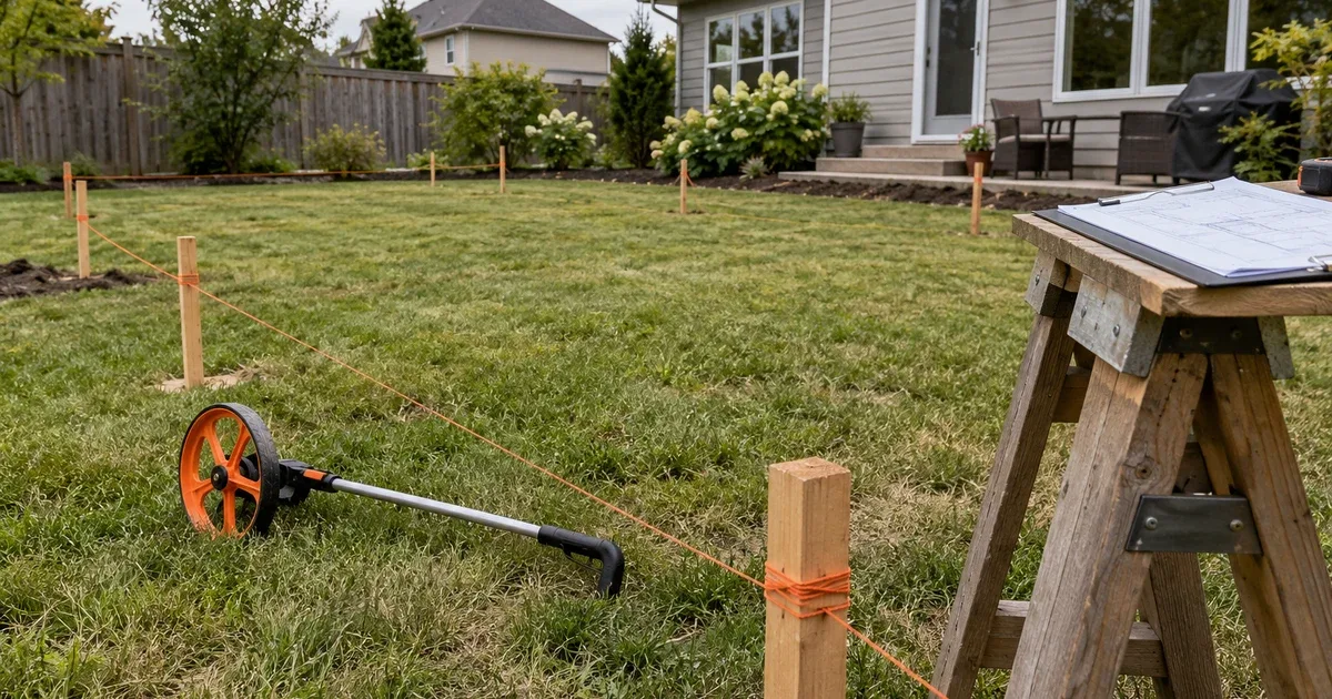
A plot plan for permit (most offices use "site plan" and "plot plan" for the same sheet) locates the proposal relative to the parcel, the existing structures and the site features that matter for review. It answers one question: where does the new work go?
Start with the base. Use a survey, a recorded plat or another record the reviewing office accepts, and keep its source and date on the sheet. A parcel map screenshot is fine for orienting yourself, but it does not establish surveyed boundaries or easements.
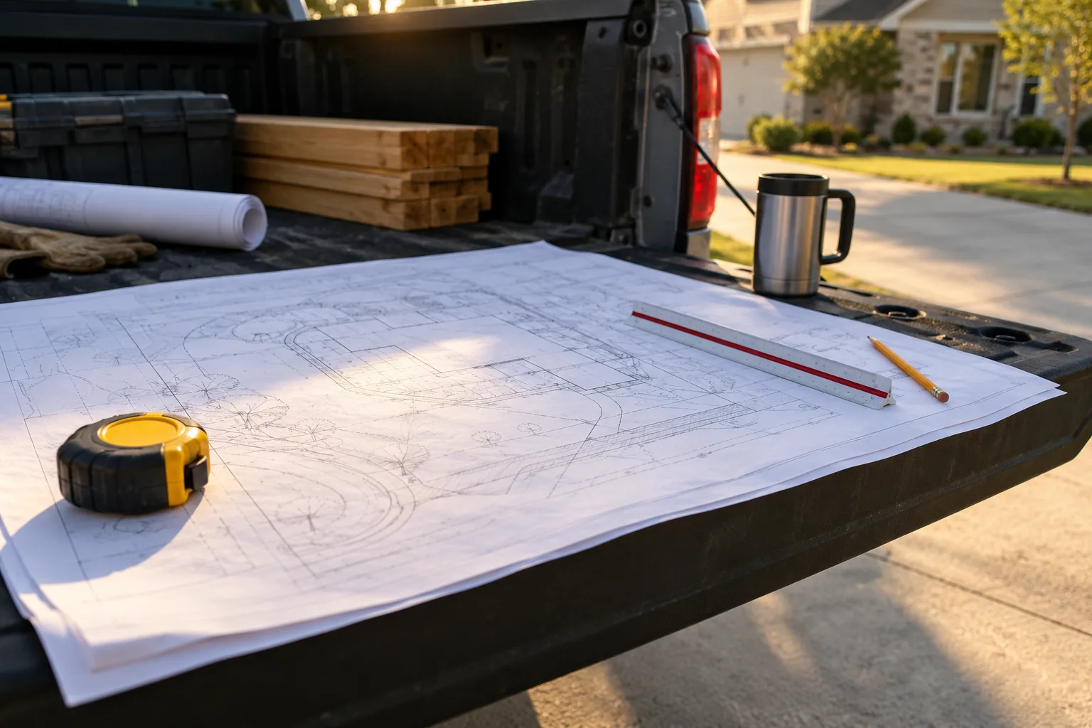
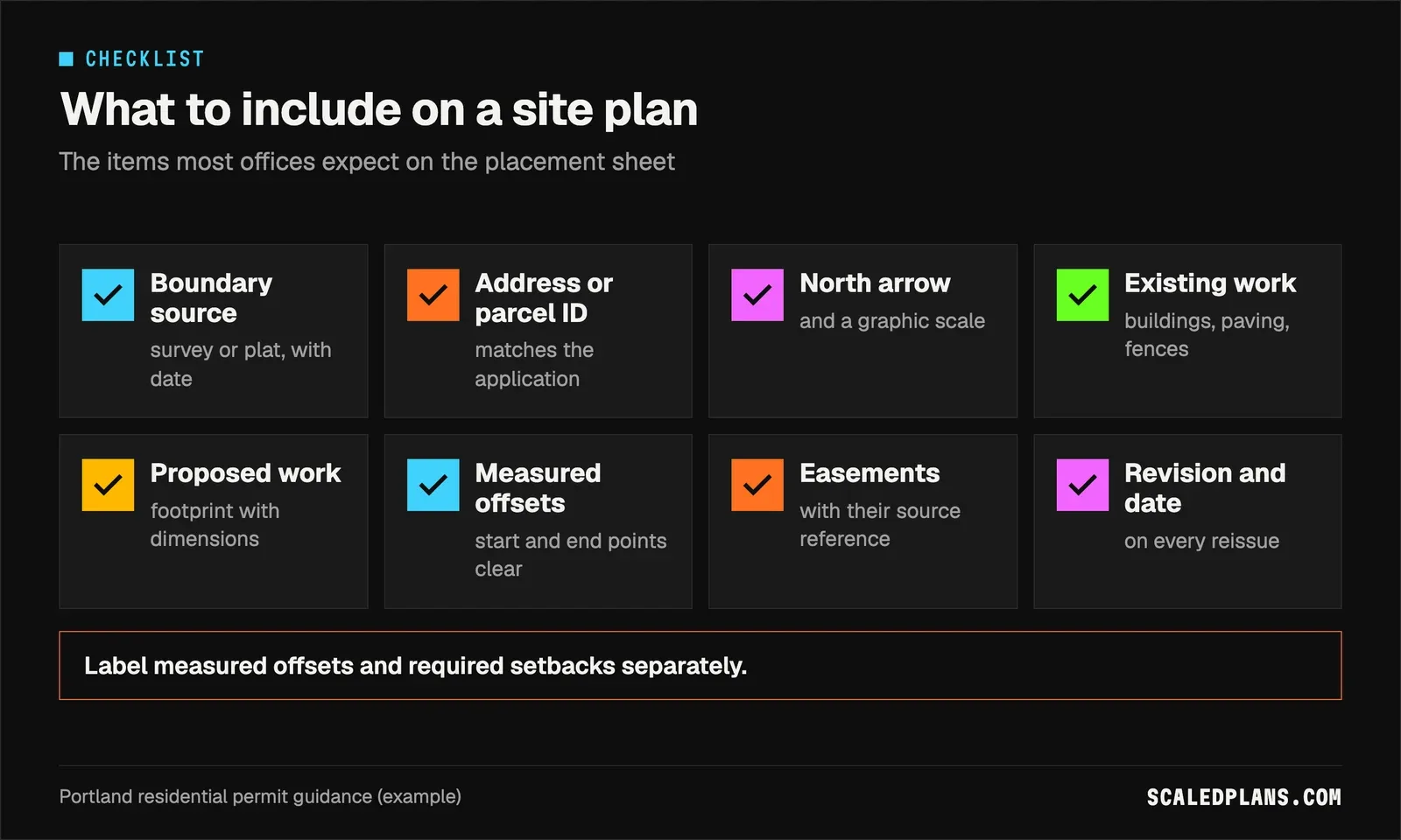
On top of that base, every site plan needs the same core items:
- The address or parcel reference, matching the application form.
- Boundary dimensions, a north arrow and a readable scale.
- Existing work, proposed work and removals, told apart with labels or a legend that survives black and white printing.
- The proposed footprint with its dimensions, plus distances to the relevant lot lines.
- Projections such as stairs, eaves and landings, drawn and dimensioned on their own instead of hidden inside a rectangle.
- Known easements and utility corridors, with their source.
Portland's residential building permit plans page is a good example of how one office separates the site plan from the other drawings, and its sample site plan shows the kind of placement detail a reviewer may ask for. Treat both as examples, not national rules. Your permit office's current checklist governs. For a Houston property, the City of Houston permit packet guide starts with jurisdiction and scope before you prepare the site sheet. If you need help reading the source sheets themselves, the blueprint reader guide walks through scales, callouts and sheet references.
Worked example: a 16 x 12 ft deck on a 60 x 100 ft lot
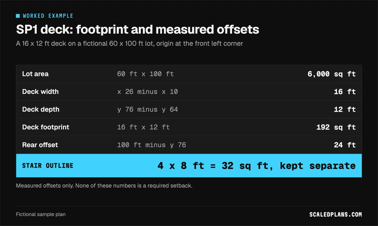
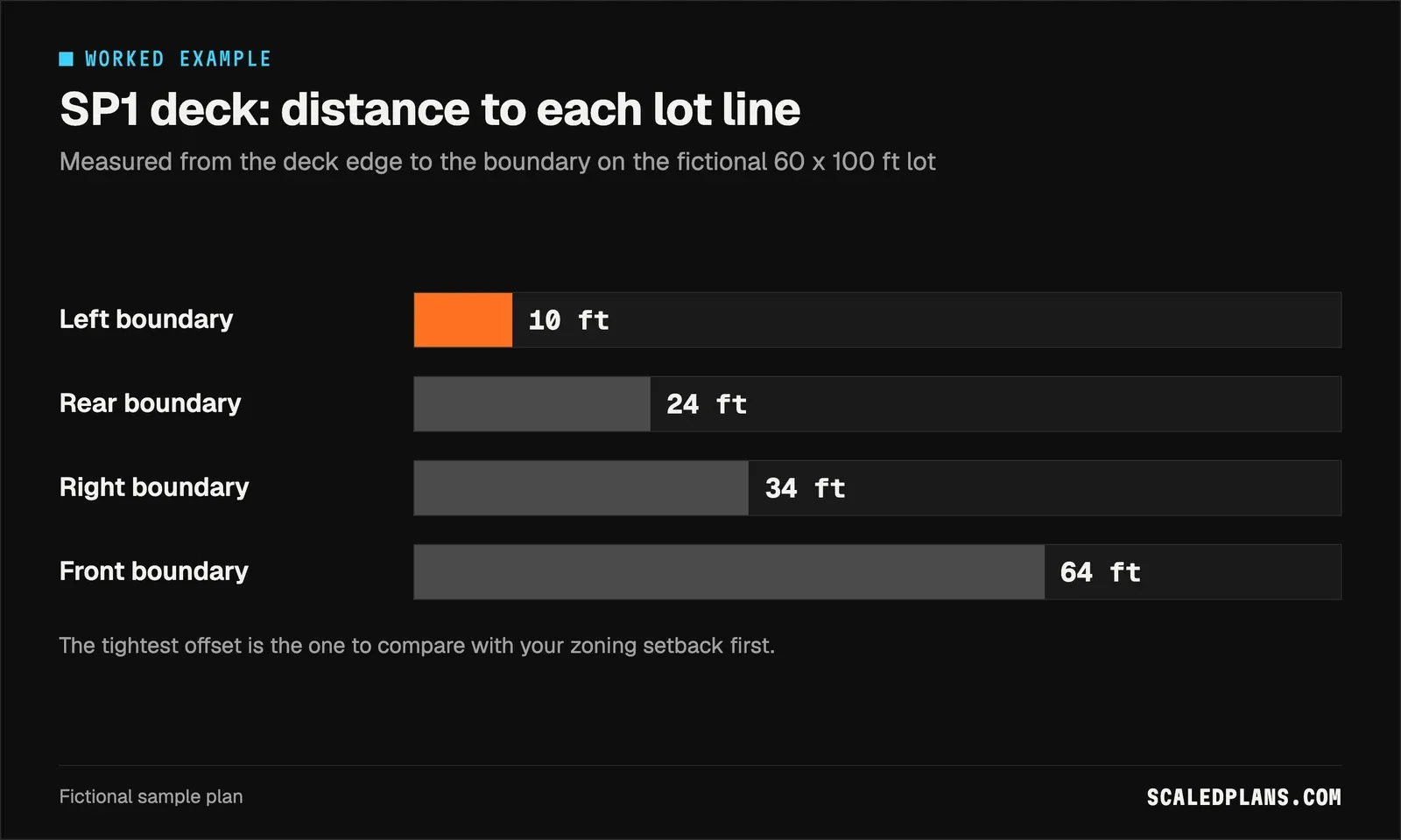
The SP1 sample is a fictional 60 x 100 ft lot with its origin at the front left corner. The proposed deck runs from x = 10 to x = 26 and from y = 64 to y = 76. Every number below comes from those four coordinates and the lot size.
| SP1 element | Calculation | Result |
|---|---|---|
| Lot | 60 x 100 | 6,000 sq ft |
| Deck width | 26 minus 10 | 16 ft |
| Deck depth | 76 minus 64 | 12 ft |
| Deck footprint | 16 x 12 | 192 sq ft |
| Left offset | deck left edge at x = 10 | 10 ft measured |
| Right offset | 60 minus 26 | 34 ft measured |
| Rear offset | 100 minus 76 | 24 ft measured |
| Stair outline | 4 x 8 | 32 sq ft, drawn separately |
Two habits make this example useful. First, the stair and landing stay as their own 32 sq ft outline, because some local coverage definitions count projections differently from the deck itself. Second, every offset says "measured". None of these distances is a required setback, and none of them establishes a legal boundary.
If you print the sheet at a different size, check the graphic scale before anyone scales a dimension off paper. A scale bar survives resizing. A "1 in = 20 ft" note does not.
How to draw a site plan for a permit
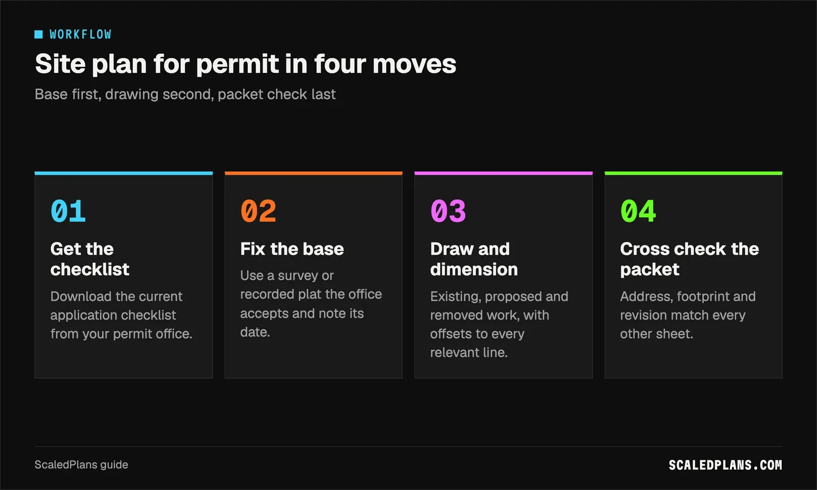
- Get the current checklist
Download the application checklist for your exact project type from your permit office. Note which boundary source, scale and sheet size they want.
- Fix the base
Pull the survey or recorded plat from your closing documents or the records office. Write its source and date on the sheet before you draw anything else.
- Draw existing and proposed work
Draw the lot lines, the existing buildings and paving, then the proposed footprint. Mark removals clearly.
- Dimension every offset
Measure from a clear point on the proposal to each relevant lot line. Draw projections like stairs and eaves as separate outlines with their own dimensions.
- Add scale, north arrow and revision
Add a graphic scale, a north arrow and a revision date. Then compare your offsets with the setbacks your zoning office lists.
- Cross check the packet
Confirm the address, footprint and revision match every other sheet in the application before you submit.
Site plan by project: fence, pool, shed, ADU or solar
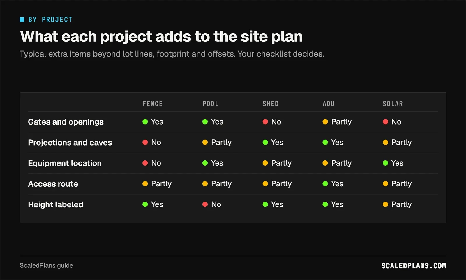
The core sheet stays the same. What changes is the extra detail each project type invites.
| Project | What to show or check |
|---|---|
| Fence | Each run with endpoints, gates and swing direction, height and material if asked |
| Pool | Water outline vs outer deck, barrier and gates, equipment location |
| Shed | Footprint, roof overhangs, height and use, offsets to lot lines |
| ADU | Both buildings, access route, utility routes marked as unresolved |
| Solar | Array location, equipment positions, roof layout coordinated with other sheets |
| Deck | Footprint, stairs and landing as a separate outline, footing locations |
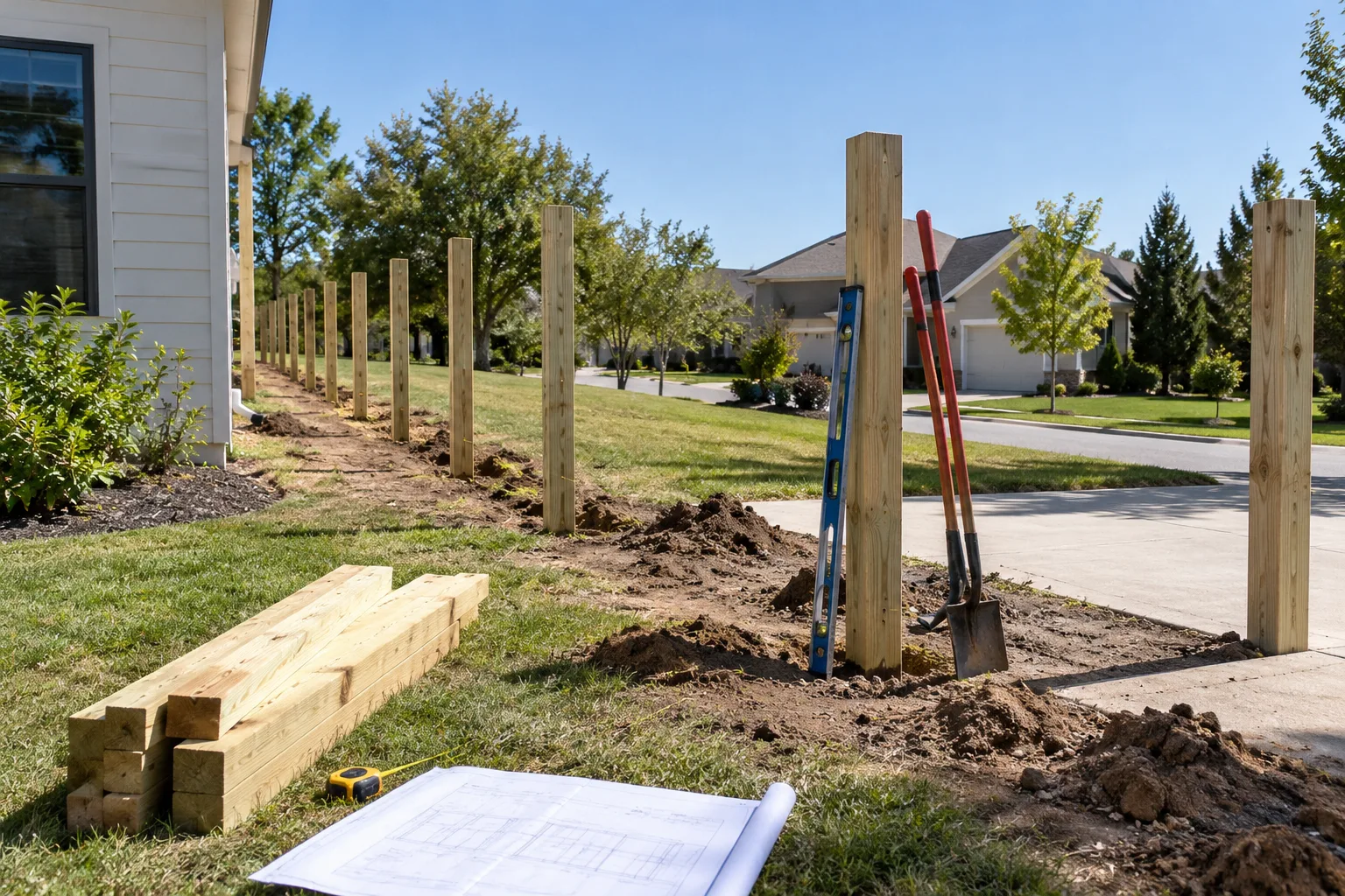
Fence permit site plan. Show each run, its endpoints and its relation to the property lines. Separate retained fence from new and removed segments. A corner lot, a driveway entrance or a shared boundary can raise visibility and access questions that a backyard rectangle never shows. A fence drawn 2 ft inside the line is an example measurement, not a recommended offset.
Pool permit site plan. Keep the water outline distinct from the deck or paving around it, so the reviewer can tell what each offset measures. Show the barrier and gate arrangement where the checklist asks for it. The site sheet locates the equipment; it does not design the wiring or drainage. The single line diagram guide covers how electrical equipment gets tagged across the rest of the packet.
Shed permit drawings. Size alone does not tell you whether a permit applies, so ask. Dimension the footprint and any overhang that affects review. Keep foundation, framing and anchorage details on their own sheets. Once the building size is settled, the siding calculator checks wall and gable coverage, but it says nothing about whether the location is acceptable.
ADU site plan. Relate the new unit to the existing house, the lot lines and access. In the fictional ADU1 sample, a 20 x 30 ft unit sits on an 80 x 120 ft lot: 600 sq ft of footprint, 20 ft to the right line and 15 ft to the rear. That 600 sq ft is a footprint, not automatically living area or a permitted coverage figure. Leave utility routes and capacity marked as open until the responsible people confirm them.
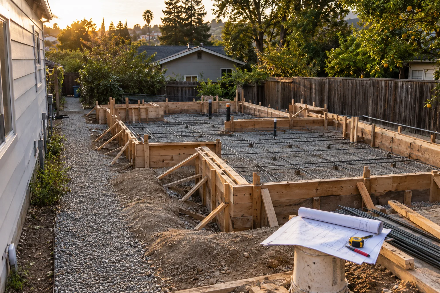
Solar permit site plan. Locate the array and the equipment, and coordinate the roof outline with the structural and electrical sheets your office requests. A roof outline is not an available array area until the designer checks pathways and setbacks. The Department of Energy's page on permitting and inspection for rooftop solar explains why local permitting matters; your jurisdiction and utility still set the actual checklist.
Drawing the site plan by hand, and where it stops scaling
You can do all of this with a survey copy, an architect scale, graph paper and a pencil. For one fence or one shed, that is often the fastest route.
- Tape the survey under tracing paper and trace the lot lines at the survey's scale.
- Draw the existing house and paving from the survey or your own measurements.
- Draw the proposal and dimension every offset, starting and ending on clear points.
- Add the north arrow, a scale bar, the source note and the date.
- Scan or photocopy at the size the office wants and check the scale bar again.
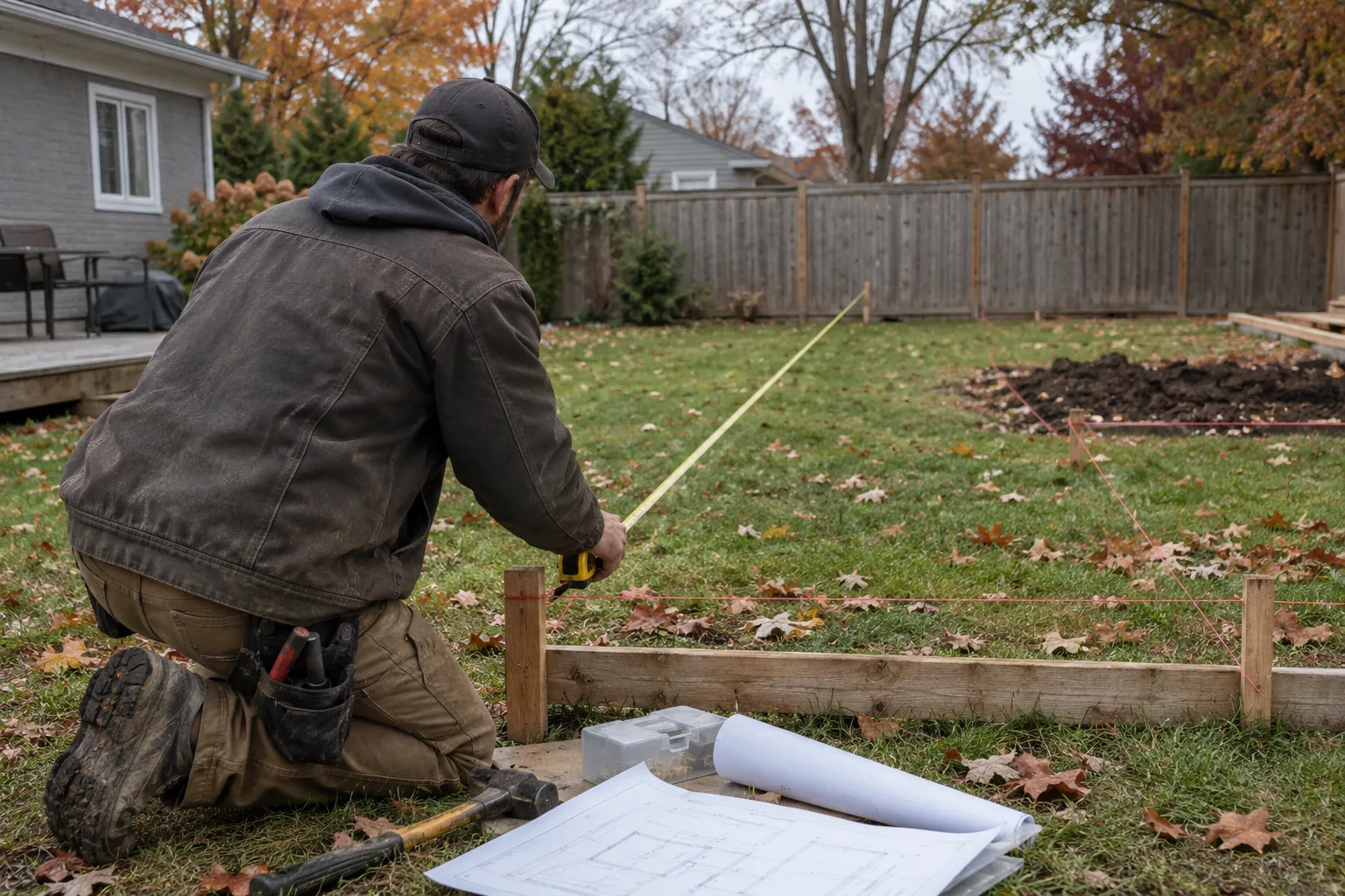
The wall shows up on revision two. The owner moves the shed 3 ft, the reviewer asks for the eave line, and you are erasing and re-measuring every offset by hand. There is no record of which edge you measured from, the footprint area and the material quantities drift apart, and a scanned survey makes every dimension a guess at the pixel. Once the placement settles, carry the same dimensions into your quantities so the drawing and the order agree.
ScaledPlans measures the plan for you, and you check every quantity before you price it. Get started when your packets outgrow the pencil.
For an attached deck, the deck permit drawings guide adds the framing plan and connection details to this site sheet. The free calculators cover the quantity side, and the drywall calculator handles interior scope once architectural dimensions exist. Converting a garage instead? The garage conversion permit guide covers the floor plans and life safety items that go with this site sheet.
Common site plan mistakes
- Drawing on a parcel map screenshot. Use a survey or recorded plat the office accepts, and write its source and date on the sheet.
- Mixing offsets and setbacks. Label what you measured as "measured" and list the required setbacks separately.
- Hiding projections in the rectangle. Draw stairs, landings and eaves as their own outlines with dimensions.
- Calling every area "coverage". Footprint, floor area and impervious coverage are different numbers; use the definition the checklist asks for.
- Dropping the scale bar. A written ratio breaks when the sheet is resized; a graphic scale does not.
Is a plot plan the same as a site plan?
For most residential permits, yes. Offices use "plot plan", "site plan" and "placement plan" for the same sheet: the lot, the buildings and the proposed work with offsets. A few jurisdictions reserve "site plan" for larger reviews with grading and drainage, so match the term on your checklist. If you are new to the drawing itself, this site plan explainer compares it with floor plans and surveys and works through a lot coverage example.
Do I need a surveyor to draw a site plan?
Not always. You need a boundary record the office accepts, which is often an existing survey or recorded plat. You need a surveyor when there is no reliable record, the boundary is disputed, or the proposal sits close to a setback line.
What scale should a site plan be drawn at?
Use the scale your checklist names, and pick one that fits the whole lot on the required sheet size with readable dimensions. Always add a graphic scale bar, because a written ratio stops being true the moment the sheet is resized or scanned.
A site plan for permit locates your proposed work on the lot with measured offsets on top of a boundary record the office accepts. The habit that matters most is getting that base right and labeling offsets as measured, so the reviewer can compare them with the rules without guessing. Draw your next one from the checklist above, and when the quantities follow, try the calculator or Get started.
Frequently asked questions
Many permit offices accept owner-prepared site plans for simple residential projects such as fences, sheds and attached decks. The drawing still needs an accepted boundary source, a north arrow, a scale, dimensions and measured offsets. Some projects and jurisdictions require a licensed surveyor or designer, especially when a boundary is uncertain or an offset is tight, so ask your permit office before you start drawing.
Get the current checklist for your project type, then pull your survey or recorded plat as the base. Draw the lot lines, existing buildings and the proposed work, dimension the footprint and its distances to the lot lines, and add a scale, north arrow and revision date. Coordinate any framing, electrical or architectural sheets the office asks for, and make sure every sheet shows the same address and footprint.
Check your closing documents for a survey or recorded plat. If you cannot find one, contact the surveyor who prepared the original or ask your county records office. Confirm with the permit reviewer which record they accept. A parcel website or an address search can help you orient yourself, but it does not establish verified legal boundaries or easements.
A simple example is a 60 x 100 ft lot with an existing house and a proposed 16 x 12 ft deck. The sheet shows the lot lines, the house, the deck at 192 sq ft, a separate 4 x 8 ft stair outline, a north arrow, a graphic scale and the measured offsets: 10 ft to the left line and 24 ft to the rear. Those offsets describe geometry, not required setbacks.
Depending on the project and local rules, an owner, a drafter, a designer, an architect or a licensed surveyor may prepare it. Simple accessory projects are often owner drawn. New homes, ADUs and projects near a disputed or tight boundary more often need a professional. The reviewing office decides what qualifications it requires for your application.
Include the boundary source and date, the address or parcel reference, lot dimensions, existing structures, the proposed work with dimensions, measured offsets to the relevant lot lines, known easements, a north arrow, a graphic scale and a revision date. Add project details from your local checklist, such as fence gates, pool barriers and equipment, ADU access routes or solar array locations.
Put it on your next bid
Plans in. Checked quantities out.
Upload the plan you are bidding, review every quantity on the drawing and export the list.
Share article
About the author
Founder
Oleh Onysko founded ScaledPlans and builds the product: how plans are measured, what each document includes and how every number stays checkable on the drawing.
More articles
 Permits & site plans · 10 min
 City of Houston permits: Prepare your residential packet
Start with the address and scope, then assemble a consistent residential permit packet. Includes a worked addition example and a review checklist.
 Permits & site plans · 12 min
 Garage Conversion Permit: 5 Steps and the Plans You Need
Turning a garage into a room or an ADU almost always needs a garage conversion permit. See what the permit office checks, what the plan set shows, a worked 400 sq ft example and why changing less gets you through faster.
 Permits & site plans · 12 min
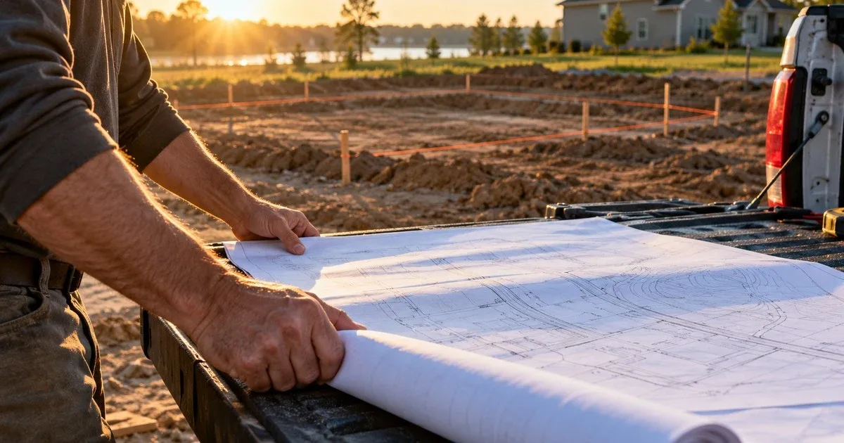
 Site Plan Explained: 10 Items to Include, With an Example
A site plan is a scaled top-down drawing of a whole lot: boundaries, buildings, paving, utilities and the distances between them. Here is what to include, a worked lot coverage example and who can draw one.
 Permits & site plans · 13 min
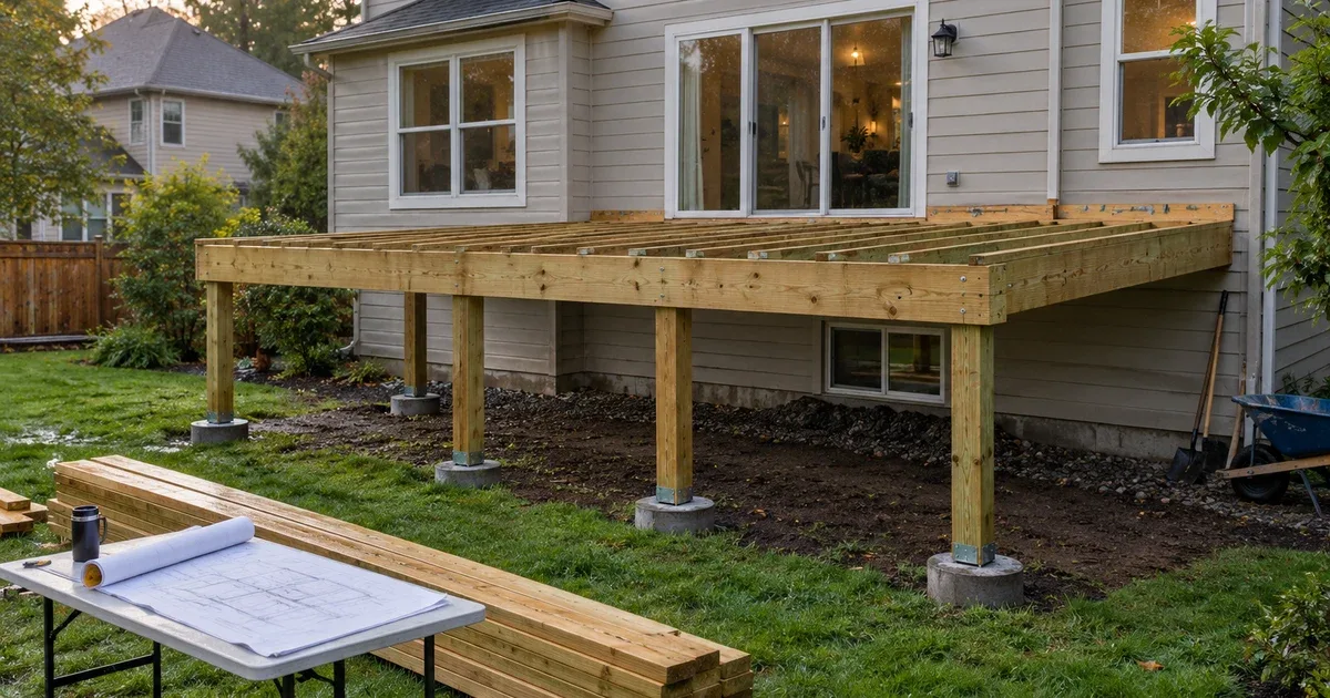
 Deck Permit Drawings: 3 Sheets and a Worked 16x12 Deck
Deck permit drawings come down to three sheets: a site plan, a framing plan and connection details. This guide builds all three around one fictional 16 x 12 ft ledger deck, with every span, footing and guard number traced to a table you can open.