Free tool · HVAC
Duct Sizing Calculator
Solve equal-friction diameter, check velocity and compare a rectangular duct at the same airflow.
UpdatedLoading the calculator…
At 400 CFM and 0.10 in. w.c. per 100 ft, the equation gives about 9.8 in. calculated diameter. Rounding up selects a 10 in. round duct, with roughly 733 fpm velocity. This equal-friction worksheet is a sizing step, not a complete Manual D design. Establish the room or system load with the HVAC load calculator before deciding how much air the duct must carry.
How to use this duct sizing calculator
Enter the design inputs
Solve equal-friction diameter, check velocity and compare a rectangular duct at the same airflow.
Inspect friction and velocity together
Read the calculated round diameter, selected standard diameter and resulting velocity. Compare the rectangular equivalent while retaining the chosen aspect ratio and airflow.
Save the distribution assumptions
Record airflow, friction target and dimensions together. A complete duct design also needs the system pressure budget, fittings and route information beyond this worksheet.
Solve the equal-friction equation for diameter
The round-duct approximation used here is pressure loss per 100 ft equals 0.109136 times airflow to the power 1.9, divided by diameter to the power 5.02. Airflow is in cubic feet per minute and diameter is in inches. Solving for diameter gives the fifth-root-style expression shown in the result panel. The coefficient is tied to those units; substituting liters per second or millimeters without conversion produces a meaningless result.
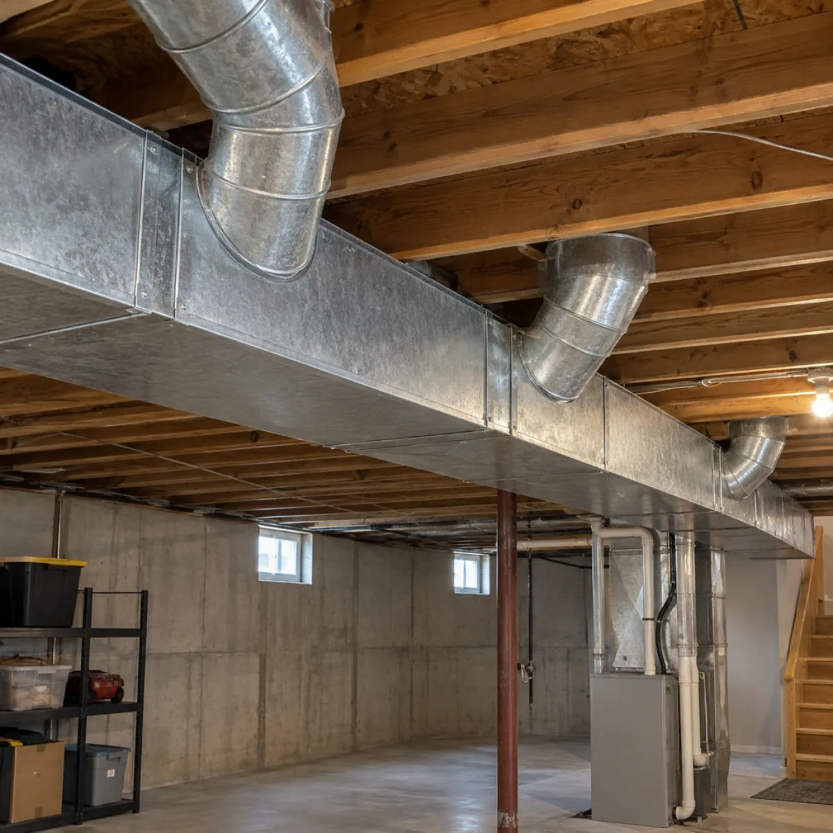
With 400 CFM and a friction rate of 0.10 in. water column per 100 ft, the calculated diameter is close to 9.8 in. The tool rounds upward to the next diameter in its explicit stock-size list, selecting 10 in. That rounding means the actual straight-duct friction will be at or below the target under the same assumptions. The list is a practical set of sizes, not proof of local supplier availability.
The equation is an approximation for metal duct under standard air conditions. Flexible duct compression, roughness, altitude and fittings change performance. Use the AC tonnage calculator for equipment screening after the load calculation, but do not make nominal tonnage the only airflow input. The system's selected coil, blower and sensible-load requirements determine the airflow that the distribution design must deliver. The Manual J report guide explains why individual room loads are needed before assigning distribution airflow.

Check velocity and rectangular equivalent diameter
Velocity is airflow divided by duct cross-sectional area. Convert the nominal round diameter from inches to feet, calculate the circular area, then divide CFM by that area. A 10 in. duct has about 0.5454 sq ft of area, so 400 CFM produces approximately 733.39 ft per minute. The velocity should be reviewed for the branch, trunk, return and noise conditions rather than judged against one universal residential limit.
For rectangular duct, the Huebscher equivalent-diameter relation is 1.30 times the product of width and height to the power 0.625, divided by their sum to the power 0.25. Both dimensions are in inches. This friction-equivalent diameter is not the diameter of a circle with equal cross-sectional area. The calculator shows both the equivalent diameter and the actual rectangular velocity so the two ideas do not get confused.
The default 14 by 8 in. rectangle has 112 sq in. of area. At 400 CFM its velocity is about 514.29 fpm. Use the equivalent diameter in the friction equation to compare pressure loss. If the route needs a framed chase, coordinate its outside dimensions and clearance with the framing calculator; the internal air passage does not include insulation, fittings or construction tolerances. Coordinate installation scope with the electrical estimating guide where selected air-handling equipment needs new electrical work.
Calculate room CFM from sensible load
The room-airflow step divides sensible Btu/h by 1.08 times the room-to-supply temperature difference. A room with 6,375 Btu/h sensible load and a 20°F difference needs approximately 295.14 CFM under the standard-air assumption. That result is displayed separately from the airflow input at the top of the widget. Enter it as the duct airflow when you want to size that branch; it does not silently overwrite a system or trunk value.
Use sensible load in this equation. Total cooling includes latent moisture removal, which is not handled by the simple temperature-difference balance. Supply temperature should reflect the selected equipment and system operation, not an arbitrary temperature chosen to make the duct smaller. Heating airflow, minimum equipment airflow and room comfort constraints can also affect the final design.
A complete Manual D process distributes air according to room loads and available blower pressure, then checks the longest effective path and balancing needs. Adding every room's peak without considering the system design can create another mismatch. The drywall calculator can help record ceiling area and openings during coordination, but grille cutouts do not determine required room airflow. Keep the load worksheet, duct schedule and reflected-ceiling plan linked by room names and revision dates.
Derive friction rate from the available pressure budget
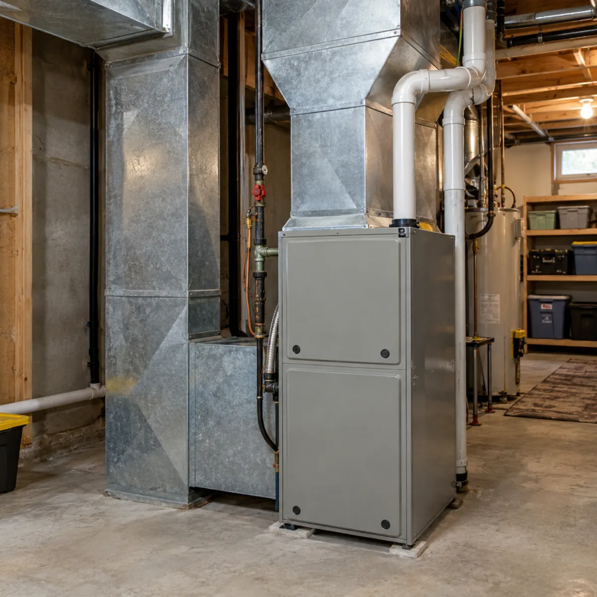
The friction-rate input should come from the distribution design. Available static pressure is what remains after accounting for components such as the coil, filter, grilles and other devices at the selected airflow. Effective duct length includes straight runs and the equivalent lengths or loss coefficients of fittings along the controlling path. A convenient 0.10 setting is useful for this worked example, but it is not a universal residential design target.
For an equal-friction system, available pressure divided by total effective length, multiplied by 100, provides a starting friction rate in inches of water per 100 ft. This widget accepts the resulting rate; it does not invent a pressure budget from floor area. Tight elbows, restrictive transitions and poorly extended flex can use up pressure that the straight-duct equation does not see.
Document fittings and access while the route is still adjustable. A rectangular equivalent can fit a shallow space yet introduce transitions that offset its apparent advantage. Check fan data, register performance, sound and balancing before construction. Coordinate motor and air-handler circuits in the panel schedule template, and use the electrical load calculator for service-demand review. A successful duct calculation and a successful electrical calculation answer different questions about the same equipment.
Check the math
Worked example: 400 CFM, 10 in. nominal round
Keep 400 CFM, friction 0.10, and a 14 × 8 in. rectangular comparison. The room-airflow example is independent and uses 6,375 sensible Btu/h with a 20°F room-to-supply difference.
| Check | Formula | Result |
|---|---|---|
| Round diameter | (0.109136 × 400^1.9 / 0.10)^(1/5.02) | About 9.8 in. |
| Nominal selection | Next listed size at or above result | 10 in. |
| Round velocity | 400 / (π × (10/12)^2 / 4) | 733.39 fpm |
| 14 × 8 velocity | 400 / (112/144) | 514.29 fpm |
| Room airflow | 6,375 / (1.08 × 20) | 295.14 CFM |
Duct Sizing Calculator questions
How to calculate duct sizing?
Establish design airflow and an available friction rate, solve the round diameter equation, round up to a listed size and check velocity. Then verify fittings, pressure budget, noise and room delivery in the full duct design.
What is the rule of thumb for duct sizing?
A single airflow-per-size shortcut hides friction and installation conditions. This tool uses airflow and friction rate explicitly. The default 0.10 in. w.c. per 100 ft is a worked assumption, not a rule for every system.
How many CFM will a 12x12 duct carry?
There is no single capacity without a velocity or friction target. Its 1 sq ft cross-section carries 600 CFM at 600 fpm. Enter 12 by 12 in. above to compare friction at your chosen airflow.
How many CFM will a 14x8 duct carry?
Its cross-section is 112/144 sq ft. At 400 CFM, velocity is about 514.29 fpm. A design must also check equivalent diameter, friction loss, fittings and the pressure available from the blower.
How many CFM can a 16x10 duct carry?
The area is 160/144 sq ft, so 600 fpm corresponds to about 666.67 CFM. That is an area-times-velocity example, not an approved airflow rating. Pressure loss and installation still govern.
What is the 2 foot rule for ductwork?
The phrase is used for different fitting and takeoff separation practices, not one universal sizing equation. Use the applicable Manual D fitting data and manufacturer installation details for the actual arrangement. Straight spacing alone does not establish capacity.
Sources
- ASHRAE Fundamentals, Chapter 21: Duct Design: Friction loss, fitting losses and equivalent-diameter concepts.
- University of Texas HVAC project: Equal Friction Method: Reproduces the 0.109136 q^1.9 / d^5.02 equation used in this worksheet.
- ACCA Manual D, Residential Duct Design: Complete residential duct design process; the widget is one simplified equal-friction step.
Link to this tool
Share the calculation method with your crew. This link opens the worksheet with its example inputs.
Next on the job
Keep your load assumptions with the project.
Start a project brief with the measurements and scope you have checked in this duct sizing calculator.