Project guide · HVAC
Manual J Calculator
Try an ACCA Manual J-style block-load estimate, then check what a complete room report needs.
UpdatedLoading the calculator…
This Manual J calculator starts with a 1,347 sq ft fictional home, 151 ft of exterior perimeter and 187 sq ft of windows. Change those inputs in the worksheet. It uses the same transparent equations as our HVAC load calculator, with a different sample so you can compare assumptions. This is an ACCA Manual J-style block-load estimate, not a Manual J report. It does not model individual room orientation, duct losses or a ventilation system. The guide below explains the additional information a complete calculation needs and how to keep the results separate from equipment selection.
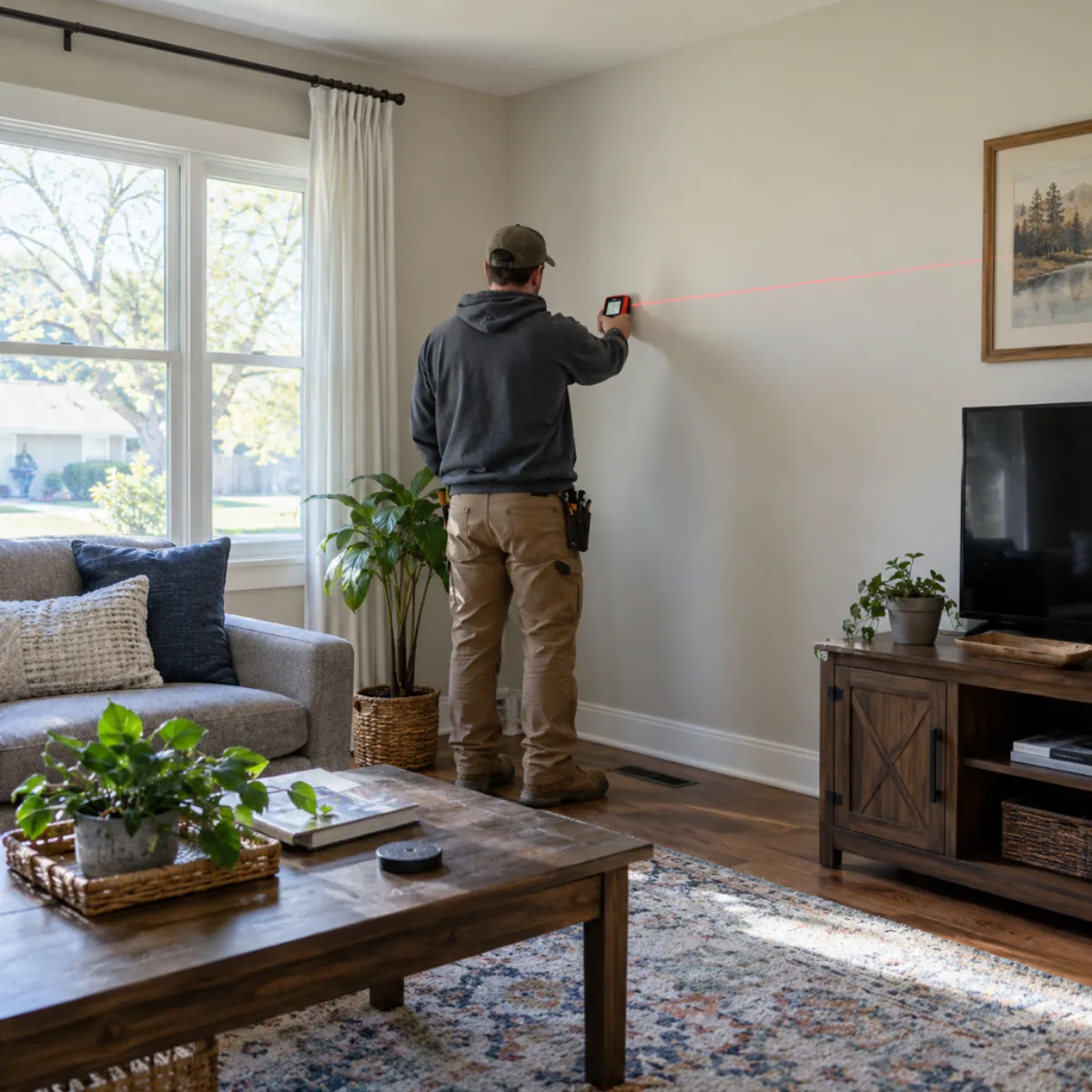
How to use this manual j calculator
Enter the building assumptions
Replace the fictional area, perimeter, glazing and temperatures with your documented values. Expand the envelope inputs and check each thermal property rather than treating an era label as a measured construction detail.
Read the substituted equations
Compare conduction, infiltration, solar, internal gains and moisture load. Change one uncertain variable at a time to see its effect. Preserve sensible and latent results separately when recording the cooling estimate.
Prepare the full calculation inputs
Collect the room schedule, orientation, design conditions, envelope details, ventilation and duct information required for a complete report. Have the building inputs and calculation method reviewed before equipment selection and distribution design.
Manual J calculator free: understand the block estimate
The widget estimates heating and cooling for one combined building block. It adds heat transfer through walls, windows, ceiling and floor, then includes simplified infiltration, solar and internal gains. The cooling result separates sensible heat from latent moisture load. You can inspect each substituted equation instead of relying on a fixed floor-area multiplier. The worksheet runs in your browser and can be used without creating an account.
Its starting home is fictional: 1,347 sq ft, 151 ft of perimeter, 8.5 ft ceilings, 187 sq ft of glazing and four occupants. Summer temperatures begin at 93°F outside and 75°F inside; winter begins at 21°F outside and 70°F inside. These are sample conditions, not weather data for an address. Modern-era assembly values are editable assumptions. Confirm the building construction before retaining any preset value in a project record.
Use the HVAC load worksheet to explore the same method with another example. The two pages should agree when their inputs match. Neither converts a block total into room loads or an approved report. A full Manual J calculation needs a more detailed building model, documented design conditions and the appropriate procedure. Treat this first result as a way to organize questions for that calculation.
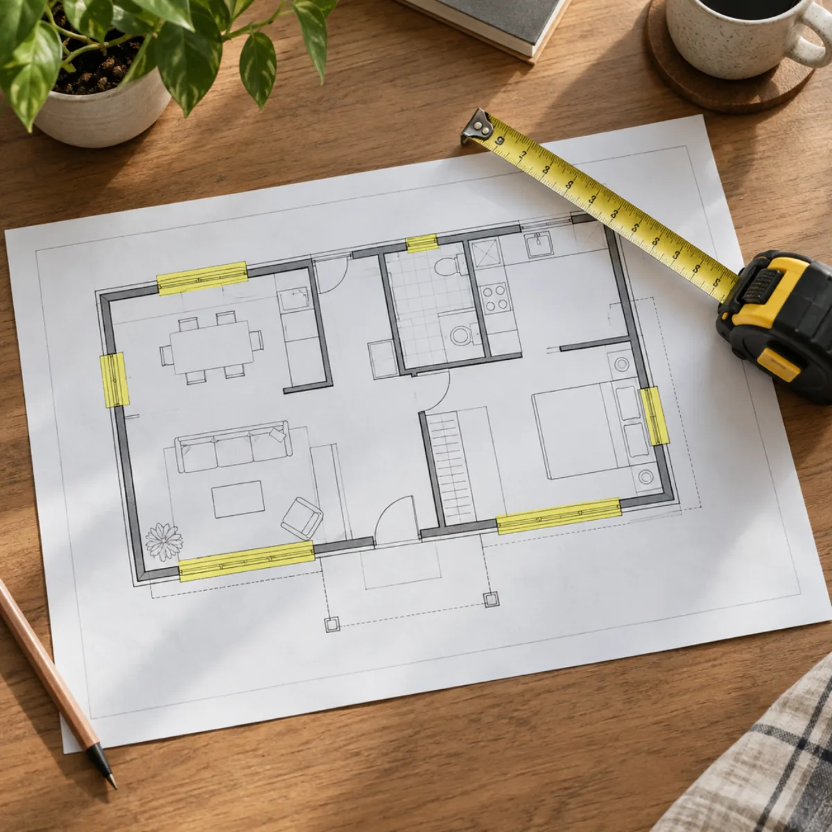
ACCA Manual J design conditions and Table 1A
Design temperature is a selected calculation condition, not today's forecast or the most extreme temperature someone remembers. For a complete residential Manual J calculation, identify the project location and the applicable design conditions from Manual J Table 1A or the method's accepted weather data. Record indoor conditions as well. The temperature differences influence heating and cooling differently, while humidity information affects the latent side of cooling.
The Department of Energy's HVAC right-sizing material illustrates the use of Manual J design data and the consequences of input choices. Read those references alongside the ACCA procedure; copying this page's 93°F sample into every project would discard the location decision. Keep the source, selected station or location and any accepted adjustment with the report. Where an authority specifies a design condition, reconcile that requirement before completing the model.
Geometry also needs a reliable source. The blueprint reader guide explains how to trace room dimensions, elevations and revisions. A conditioned area should follow the building boundary used in the load model, not a real-estate listing rounded to the nearest hundred square feet. Resolve whether a garage, attic or crawlspace is inside that boundary. Mark unknown construction and climate inputs explicitly so the reviewer can find them before equipment selection begins.
Room-by-room inputs behind a full Manual J report
A room calculation begins with each room's dimensions, ceiling height, exterior surfaces and exposure. Windows need dimensions, orientation and performance information; shading and overhangs can change the solar contribution. Walls, roofs and floors need the correct assembly and adjacent-space conditions. The software cannot infer concealed insulation reliably from a photograph of the finished wall. Existing homes may require field measurements and construction records to resolve those inputs.
Infiltration and ventilation also need defensible assumptions. The block widget's air-change rate produces a simple airflow estimate, but it does not represent every ventilation arrangement or infiltration procedure in Manual J. A complete job should identify the relevant system, leakage information, ducts and the spaces through which they run. Room distribution matters because two rooms with equal floor area can have different glazing, orientation and exposure.
For an addition or detached unit, coordinate the building footprint with the site plan guide, while obtaining actual room and envelope information from architectural sheets. Do not use the footprint alone as the load input schedule. Preserve a distinction between measured values, documented product data and assumptions needing review. The final report should expose that record, identify its calculation method and provide both room-level results and the appropriate whole-building summary for the design tasks that follow.
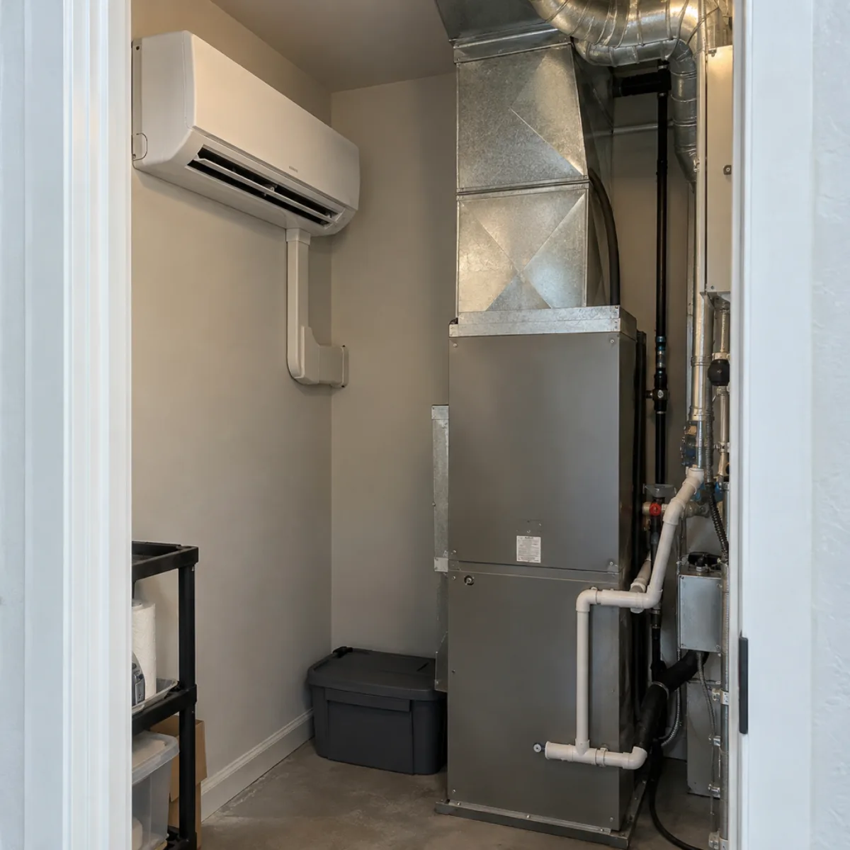
Manual J software: read the report before choosing equipment
A readable report should make its inputs reviewable, not merely print a large total on the first page. Look for project identification, design conditions, room geometry, assembly information and sensible and latent cooling results. Check the calculation engine and any required approval separately from the appearance of the PDF. ACCA publishes information about approved software; this worksheet does not claim that status.
Our MJ1 sample report structure illustrates two room rows, an input checklist and a review record. It explicitly has no identified calculation engine or reviewer and incomplete inputs. Its room numbers demonstrate how a report can be organized, not calculated performance for the home shown in the widget. A polished layout cannot resolve missing measurements, and the sample should not be submitted as a completed project calculation.
After a reviewed load calculation, move to the AC tonnage calculator for a separate capacity comparison. It converts thermal load into tons and illustrates a screening step; actual equipment selection needs manufacturer performance at the design conditions. Keep each document's purpose visible. The load report describes the building demand, the equipment selection describes a proposed machine, and the distribution design explains how conditioned air reaches the rooms. Renaming one output does not complete the other tasks.
Keep sensible load, latent load and electrical input distinct
Sensible cooling changes air temperature; latent cooling addresses moisture. This distinction matters when comparing a building's cooling requirement with equipment performance. A total cooling number alone can hide a mismatch between these two demands. In the block estimate, solar and assembly gains feed the sensible calculation, while the stated moisture difference and occupancy assumptions contribute to latent load. The coefficients and simplifications are shown with the widget result.
Thermal output also differs from electrical input. A cooling capacity expressed in Btu/h cannot be copied into the electrical load calculator as watts or volt-amperes. Obtain the actual selected equipment's electrical nameplate data and the appropriate demand method. A coefficient of performance describes a relationship between thermal output and power input under specified conditions; it is not a substitute for a product's required electrical data.
For room airflow, the duct sizing calculator illustrates a sensible-load relationship using airflow and a temperature difference. It is a separate distribution calculation. Do not distribute whole-house cooling evenly by room count or assume every room needs the same outlet. Record room sensible loads, delivery temperatures and the system design assumptions before reviewing airflow. This keeps moisture control, building heat gains, equipment power and air distribution from being collapsed into one misleading number.
Review uncertainty without stacking sizing allowances
An uncertain input should lead to a measurement or a documented assumption, not an unexplained increase in the final load. If window performance is unknown, identify which windows need labels or records. If the attic insulation cannot be confirmed, assign a field check. Adding an extra percentage to several inputs and then adding another percentage to the equipment can compound conservatism without making the building model more accurate.
Use the sample worksheet for a sensitivity comparison. Change glazing from 187 to 207 sq ft while keeping perimeter and height fixed. The model replaces 20 sq ft of opaque wall with windows and changes solar gain as well as conduction. That is a more informative comparison than assuming a larger floor area. Save both input sets with names that describe the change, and report which assumptions stayed constant.
A review package should finish with an unresolved-input list and a named next action. Match equipment identifiers to the single line diagram guide when the mechanical selection affects electrical documentation. Return to the tools index for the supporting worksheets. A completed calculation depends on verified project data and the required method, while this block exercise helps you prepare that data and understand which variables move the estimate. Coordinate the bid scope through the electrical estimating guide after the equipment is selected.
Check the math
Worked example: reconcile the MJ1 room totals
The existing MJ1 sample gives a living room and bedroom with separate heating, sensible cooling and latent cooling columns. Add each column independently: heating is 8,000 + 4,000 = 12,000 Btu/h; sensible cooling is 5,000 + 2,500 = 7,500 Btu/h; latent cooling is 1,000 + 500 = 1,500 Btu/h. Total cooling for those sample rows is 9,000 Btu/h, or 0.75 ton as a unit conversion. That number is not an equipment recommendation. These are illustrative room outputs with incomplete source inputs, unrelated to the live 1,347 sq ft block calculation above. The PDF report layout preserves the input checklist and review status alongside the totals.
| MJ1 row | Heating Btu/h | Sensible / latent cooling Btu/h |
|---|---|---|
| Living room | 8,000 | 5,000 / 1,000 |
| Bedroom | 4,000 | 2,500 / 500 |
| Column totals | 12,000 | 7,500 / 1,500 |
| Cooling conversion | Separate from heating | 9,000 / 12,000 = 0.75 ton |
Weather record
Name the design-data source and location. A sample outdoor temperature is only a placeholder for an exercise input.
Envelope evidence
Keep window labels and assembly records with the dimensions. Photographs cannot establish every concealed thermal property.
Room schedule
Separate each room and its exterior exposures. The block worksheet intentionally stops before this level of modeling.
Design sequence
Review the building load, select equipment with performance data, then design distribution. Preserve the assumptions used at each stage.
Manual J Calculator questions
What is the formula for calculating the AC load?
This block estimate sums assembly conduction, sensible infiltration, solar and internal gains, then adds latent load. Assembly conduction is U × area × temperature difference. Full Manual J uses a more detailed procedure and room-specific inputs; no single floor-area formula replaces it.
How is COP calculated?
Coefficient of performance is thermal output divided by power input when both use consistent units. State the operating conditions with the value. COP is an equipment efficiency measure, while Manual J evaluates building loads; it does not turn the block widget into an equipment selection report.
Can I use this Manual J calculator free without a login?
Yes. The embedded block worksheet recalculates in the browser with no login. Its result remains a simplified estimate with stated limitations. A complete Manual J report requires room-by-room inputs, documented design conditions and the relevant calculation procedure.
Where do the design temperatures for ACCA Manual J come from?
Use the applicable Manual J Table 1A design conditions or accepted weather data for the project location and procedure. Document indoor conditions too. The 93°F summer and 21°F winter defaults on this page are fictional exercise inputs, not a location lookup.
Does this Manual J software create a room-by-room report?
The embedded worksheet models one building block and does not create a room report. The linked MJ1 file is an authored report-layout example with incomplete inputs and no asserted reviewer. Use it to inspect the fields a complete project record should contain.
Why does the MJ1 example differ from the live block result?
MJ1 contains illustrative loads for a two-room addition, while the widget uses a separate 1,347 sq ft home. They have different purposes and inputs. Summing the sample room rows checks report arithmetic; it does not validate the widget or provide a design load for either project.
Sources
- ACCA Manual J residential load calculation: Scope of the residential load calculation procedure; this simplified worksheet is not an approved implementation.
- DOE HVAC right-sizing: calculating loads: Input discipline and Manual J design-condition references, including Table 1A.
- ACCA Manual S equipment selection: Equipment selection follows the building load calculation.
- ACCA Manual D duct design: Residential air-distribution design is a separate procedure.
Link to this tool
Share the calculation method with your crew. This link opens the worksheet with its example inputs.
Next on the job
Start with a documented building brief.
Try an ACCA Manual J-style block-load estimate, then check what a complete room report needs.