Project guide · Permits
Site Plan for Permit
Show the property, proposed work and measured offsets on one readable placement sheet.
UpdatedOn the existing SP1 sample, a 16 × 12 ft deck covers 192 sq ft, sits 10 ft from the left boundary and leaves 24 ft to the rear boundary. Those are fictional measured offsets, not required setbacks. A site plan for permit needs that distinction to stay visible. Start with an accepted boundary source, draw the existing and proposed work, then compare the proposal with your permit office checklist. This guide combines fence, pool, shed, ADU and solar placement questions so you can prepare one coordinated site record rather than chase separate generic drawings.
How to use this site plan for permit
Collect the base and checklist
Gather the survey or other accepted boundary record, proposed dimensions and the permit office requirements. Identify missing easement or site information before drawing around assumptions.
Draw and dimension the proposal
Separate existing work, proposed structures and removals. Add footprint dimensions, relevant boundary offsets, projections, scale and north arrow. State what each area calculation includes.
Coordinate the submission sheets
Check the site record against architectural and trade drawings. Resolve source questions and local checklist items with the responsible people, then issue matching revisions for the packet.
Plot plan for permit: establish the drawing base
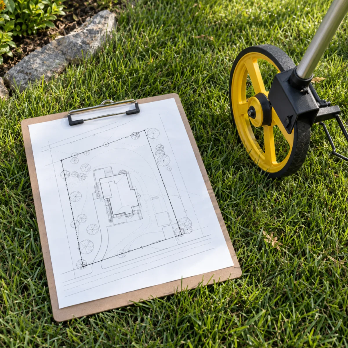
A plot plan for permit locates the proposal relative to the parcel, existing structures and relevant site features. Start with a survey, recorded plat or other base that the reviewing office accepts for your application. Keep its source and date visible. A parcel-map screenshot can help you orient yourself, but it does not by itself establish surveyed boundaries, easements or a construction-ready layout.
Show the address or parcel reference, boundary dimensions, north arrow, readable scale and revision. Distinguish existing work, proposed work and removals through labels or a legend that survives black-and-white printing. Dimension the proposed footprint and its distances to the relevant boundaries. Where projections such as stairs, eaves or landings affect the review, draw and dimension them explicitly instead of hiding them inside a simple rectangle.
Portland's sample site-plan guidance illustrates the type of placement information a reviewing office may request; its checklist is an example, not a national rule. For reading the source sheets, use the blueprint reader guide. Check with your permit office for the actual submittal requirements before finalizing the drawing. If a boundary or easement is uncertain, resolve the source question first. A neat drawing cannot improve the reliability of an unverified property reference.
Fence permit site plan: corners, gates and easements
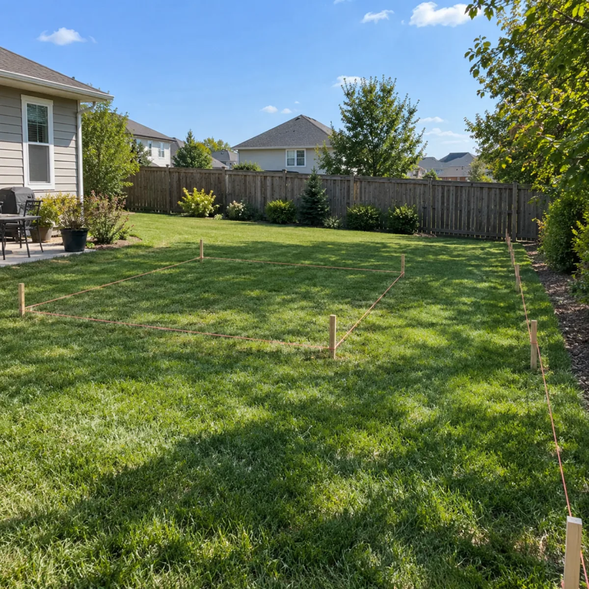
For a fence proposal, show each run, its endpoints and the relationship to the property lines. Separate existing fence retained from new or removed segments. Label proposed height and material where requested, and identify gates with their locations and opening direction. A street corner, driveway entrance or shared boundary may introduce review questions that a simple backyard rectangle does not reveal.
Known easements and utility corridors belong on the base drawing with their source references. Do not assume that placing a fence inside the property boundary resolves every restriction. Ask the reviewing office which zoning, visibility or access information applies, and keep any required supporting details separate from the placement dimensions. A fence line shown 2 ft inside a boundary is an example measurement, not a recommended or universally required offset.
Use one scale and north arrow for the overall sheet, with enlarged details clearly labeled if needed. Record each run length independently so the site drawing can support a later material takeoff without turning into one. The framing calculator is for wall-framing quantities, so it should not be used to infer fence-post spacing or structural design. Select the right calculation for the actual assembly. The permit drawing's first job remains explaining where the fence goes and what information supports that placement.
Pool permit site plan: water, barriers and equipment
A pool site plan should identify the proposed pool outline, surrounding deck or paving and the equipment location, along with existing buildings and parcel boundaries. Label the dimensions the reviewing office requests, including distances from the proposal to relevant structures and property lines. Keep the water outline distinguishable from the outer construction footprint so a reviewer can see what each offset actually measures.
Show the barrier and gate arrangement where required by the application checklist. Include known easements and site constraints rather than presenting the yard as empty space. Pool equipment can introduce electrical, drainage and access coordination, but a placement sheet does not design those systems. Identify the responsible supporting drawings and any unresolved route or equipment information.
An electrical estimating worksheet may help organize the equipment and route scope after the design is established. Use the single line diagram guide to coordinate electrical equipment identifiers, not to choose pool wiring or protective devices. Retain scale, north arrow, source date and revisions on the pool sheet just as on the base site plan. Confirm the current local pool and barrier submittal requirements with the permit office. Do not copy a barrier height, setback or equipment clearance from an unrelated sample and label it compliant for your property.
Shed permit drawings: footprint and projections
A shed proposal needs more than a floor rectangle placed in the yard. Show the proposed footprint dimensions, the location relative to existing structures and measured offsets to relevant boundaries. Identify roof overhangs or other projections when they affect the required review. Label the intended use and height where requested, and distinguish the shed from paving or storage areas that may appear nearby.
A small building's permit status depends on the local rules and the actual project. Size alone is not enough to infer that no permit or zoning review applies. Ask which supporting drawings are needed for the foundation, framing, anchorage and electrical work. Keep those construction details separate from the site placement sheet so the drawing packet has a clear division of purpose.
For an exterior material exercise, the siding calculator can check measured wall and gable coverage once the building dimensions are established. Its quantity result says nothing about whether the shed location is acceptable. Include easements, a north arrow, scale and the boundary source on the site sheet. Dimension any access route the reviewer requests, and flag unknown information for resolution. A proposal with a measured 6 ft offset still needs comparison with the applicable requirement; the number on the drawing is evidence of geometry, not a ruling on the project.
ADU site plan: access, utilities and the existing house
An ADU site plan relates the new unit to the existing home, lot boundaries, access and utility information. Show both building footprints with dimensions, and identify proposed work separately from retained structures. Add known easements and any other features required by the reviewing office. Utility routes and capacity should remain explicitly unresolved until the responsible sources establish them.
The ADU1 sample places a 20 × 30 ft unit on an 80 × 120 ft lot. Its 600 sq ft footprint is not automatically living area or a locally permitted coverage amount. The drawn right offset is 20 ft and the rear offset is 15 ft. A schematic 4 ft access route appears as an example dimension, not a fire-access or accessibility minimum. Keep these labels attached when discussing the sample.
Coordinate the architectural room plan with the Manual J calculator guide if the project includes conditioned space. The site footprint cannot supply window performance, insulation or room orientation by itself. Likewise, the site sheet does not establish ADU eligibility, service capacity or structural adequacy. Retain the north arrow and graphic scale, document the boundary source, and bring the complete local ADU checklist into the review before treating the placement sheet as part of a submission.
Solar permit site plan: roof areas and equipment locations
A solar placement drawing should identify the building or ground area involved, the proposed array location and relevant equipment positions. Show parcel boundaries and existing structures so the proposal can be located unambiguously. Ground-mounted work may need footprint dimensions and boundary offsets, while roof-mounted work needs coordination with the roof layout and the supporting structural and electrical documents requested locally.
Do not interpret a roof outline as an available array area without the required design checks. Access pathways, setbacks, roof features and other constraints depend on the applicable rules and project conditions. Mark what is known and identify what the designer must supply. Where equipment sits outside, coordinate its tag, access and route information with the rest of the drawing packet.
The single-line electrical guide and panel schedule template help explain the related documents, but neither establishes a solar interconnection design. Preserve scale, north arrow, source references and revision dates across the package. The Department of Energy's permitting resources describe the importance of local permitting and inspection processes; they do not replace the current checklist from your jurisdiction and utility. A complete site record makes the proposal easier to review while leaving equipment sizing, structural work and connection approval with their responsible design and review processes.
Plot plan for my property: reconcile the permit packet
To assemble a plot plan for my property, begin with the owner records: closing documents, an existing survey, a recorded plat or a suitable record from the local office. Ask the permit reviewer which base is acceptable for the proposed work. If the project depends on a disputed boundary or a tight offset, get the appropriate professional help to resolve it before developing a detailed placement around an uncertain line.
Use a checklist to compare the site sheet with the other permit drawings. The project address, footprint and revision should agree across the application. Identify every area calculation by definition: building footprint, floor area, paving and impervious coverage are not interchangeable labels. Keep existing and proposed totals separate until you know which local calculation is required. Do not add a waste factor to a parcel or coverage measurement.
The tools hub brings the related quantity worksheets together, including the drywall calculator for interior scope once architectural dimensions exist. Finish the site-plan review by checking all dimension endpoints, scale readability and the north arrow at the intended print size. Record open source questions rather than erasing them from the final checklist. The reviewing office decides the application requirements; your drawing should make the underlying facts and remaining questions easy to find.
Check the math
Worked example: SP1 deck placement and boundary offsets
The SP1 placement sample defines a 60 × 100 ft lot with its coordinate origin at the front-left corner. The deck extends from x = 10 to 26 and y = 64 to 76. Its width is therefore 16 ft and depth 12 ft, producing 192 sq ft. The left offset is 10 ft; the rear offset is 100 − 76 = 24 ft. A separate 4 × 8 ft stair-and-landing outline occupies 32 sq ft in this schematic geometry. Keep that projection distinct when checking local coverage definitions. The printable SP1 sheet includes a graphic scale, which should be checked after resizing. None of these distances states a required setback or establishes legal boundaries.
| SP1 element | Calculation or reference | Example result |
|---|---|---|
| Lot | 60 × 100 | 6,000 sq ft |
| Deck | (26 − 10) × (76 − 64) | 192 sq ft |
| Left offset | Deck left x = 10 | 10 ft measured |
| Rear offset | 100 − 76 | 24 ft measured |
| Stair outline | 4 × 8 | 32 sq ft schematic projection |
Boundary source
Record where parcel dimensions came from. A satellite image can orient the view without establishing the boundary.
Offset labels
Show where each dimension starts and ends. Measured offsets and required setbacks need separate labels.
Area definitions
A footprint is not automatically living area or impervious coverage. Use the definition requested for the application.
Packet review
Retain construction and utility questions on the checklist. A placement sheet does not complete every required drawing.
Site Plan for Permit questions
Can I create my own site plan?
Ask the permit office whether owner-prepared drawings are accepted for the specific application and which boundary source is required. A simple placement sheet may be possible from reliable records, but surveying, structural design and other professional work can remain separate requirements.
How to draw up plans for a permit?
Obtain the current project checklist, establish an accepted base and draw the existing and proposed work with dimensions. Add scale, north arrow, parcel information and revisions. Coordinate any required architectural, structural and trade sheets before submission.
How do I obtain a site plan for my property?
Look for a survey or recorded plat in your closing records, ask the original surveyor or contact the local records office. Confirm what the permit reviewer accepts. A parcel website or address search alone does not establish verified legal boundaries.
What is an example of a site plan?
SP1 is a fictional 60 × 100 ft lot with an existing house, a 16 × 12 ft deck and a stair outline. It shows dimensions, a north arrow and graphic scale. Its offsets illustrate geometry and are not jurisdictional setback requirements.
Who prepares a site plan?
Preparation depends on the project and local requirements. An owner, drafter, designer or appropriate licensed professional may have a role. Ask the reviewing office what qualifications and supporting documents are required for the specific application.
What should I include in a site plan?
Include the accepted boundary reference, existing and proposed structures, footprint dimensions, measured offsets, known easements, scale, north arrow and revision information. Add project-specific details from the local checklist, such as gates, pool equipment, access or solar locations.
Sources
- Portland residential building permit plans: Example jurisdiction guidance distinguishing site plans and other building drawings; requirements vary elsewhere.
- Portland sample site plan: Illustration of site dimensions, boundaries and drawing information, not a universal setback standard.
- DOE solar permitting and inspection: Context for coordinating local solar permitting and inspection.
- ScaledPlans SP1 placement sample: Fictional coordinate geometry used in the worked example.
Link to this tool
Share this guide with the person reviewing your drawings. The link keeps the worked example and source notes together.
Next on the job
Bring the property and proposal together.
Show the property, proposed work and measured offsets on one readable placement sheet.