Site Plan Explained: 10 Items to Include, With an Example
Oleh Onysko 16 October 2026 12 min read
In this article
A site plan is a scaled, top-down drawing of a whole property: the lot lines, every building, the paving, the utilities and the measured distances between them. It answers one question a floor plan never does: where does everything sit on the lot, and how far is it from the edges?
Here is what most people get backwards. The building is the least important thing on a site plan. A plain 30 x 40 ft box with exact offsets to every lot line tells a reviewer, an excavator or an estimator more than a detailed house drawn loose. The sheet is really a record of distances and areas, so that is where your care should go.
| Site plan fact | What it means for you |
|---|---|
| View | Top down, the whole lot at one scale |
| Base | A survey, recorded plat or other boundary record |
| Core content | Lot lines, buildings, paving, utilities, offsets |
| Key numbers | Offsets to each lot line, footprint and coverage |
| Common scale | 1 in = 10 ft to 1 in = 40 ft for a house lot |
| Who decides what is required | Your local permit or zoning office |
What is a site plan, and what does it show?
A site plan shows the property as a bird would see it. It covers the full parcel, not just the building, and it fixes every feature with a dimension. Builders, permit offices, utility companies and lenders all read the same sheet for different reasons.
On a residential lot, a site plan usually shows:
- The boundary. Lot lines with their lengths, the street frontage and any easements on record.
- Existing buildings. The house, garage, sheds and decks, each as an outline with its dimensions.
- Proposed work. The addition, garage, pool, fence or ADU you are planning, clearly marked as new.
- Offsets. Measured distances from each building to each lot line it faces.
- Hard surfaces. Driveways, walks and patios, because they count toward coverage in many places.
- Utilities. Water, sewer or septic, gas and electric service routes, plus the meter locations.
- Scale, north arrow and date. So anyone can measure off the sheet and know which version they hold.
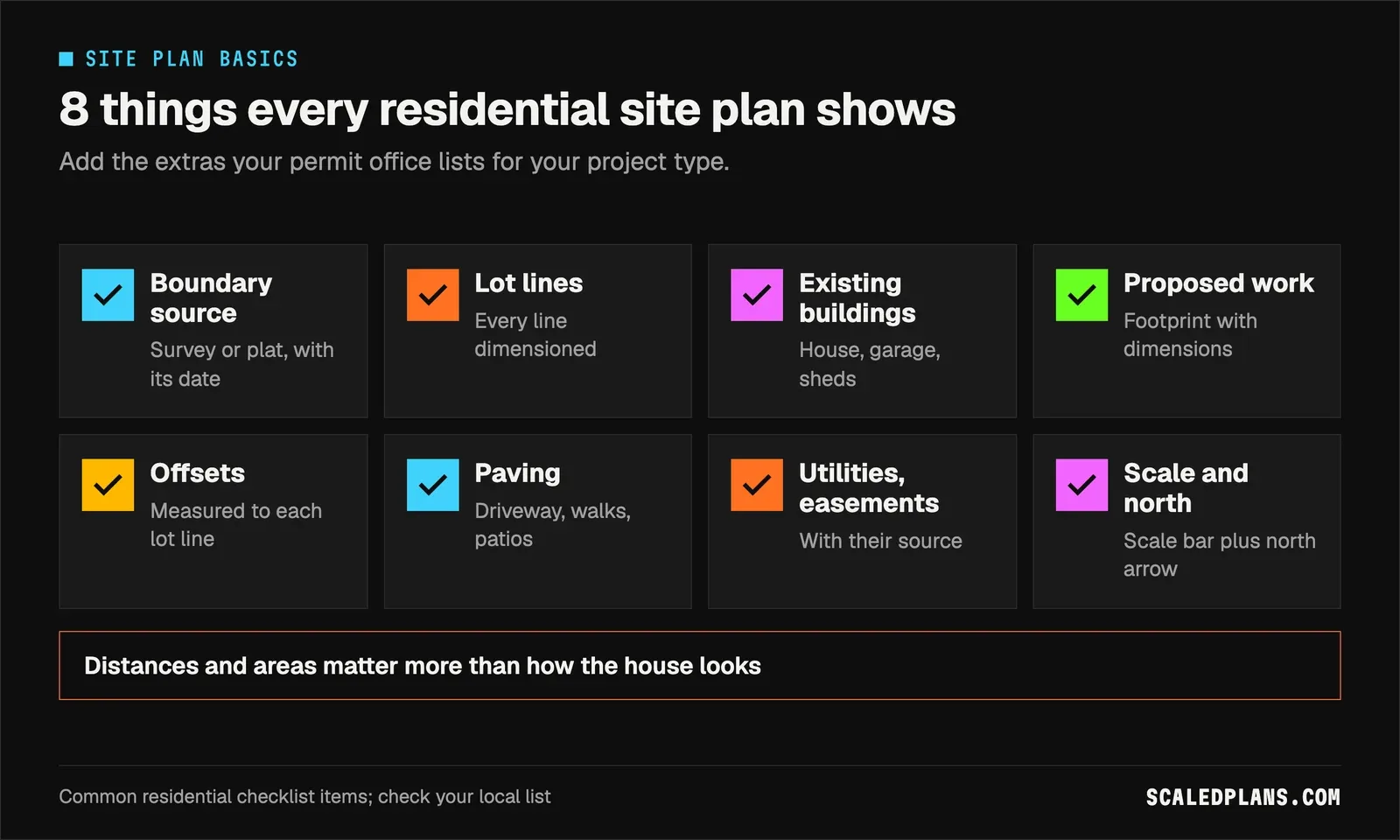
Portland's guide to drawing a site plan is a clear public example of what one office expects on the sheet. Treat it as a model, not a national rule. Each jurisdiction writes its own checklist.
Site plan vs floor plan vs survey
These three get mixed up constantly, and the mix up costs time. A floor plan shows the inside of one level: walls, rooms, doors and windows. A boundary survey is a legal document from a licensed surveyor that establishes where the lot lines are. A site plan sits on top of the survey and places the buildings and site work inside those lines.
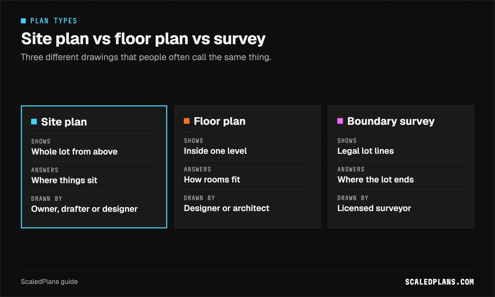
The practical rule: you can draw a site plan, but you cannot create a boundary. If your site plan is traced from a survey, the lot lines are only as good as that survey. If you need help reading the source sheets themselves, the guide to reading blueprints covers scales, symbols and sheet references.
Plot plan, site development plan and the other names
Most residential permit offices use "plot plan" and "site plan" for the same sheet. Larger projects add a site development plan with grading, drainage, parking and stormwater, usually drawn by a civil engineer. A construction site management plan is a different document again: it covers logistics during the build, like deliveries, fencing, dumpsters and erosion control, not the finished layout. Match the term your office uses on its checklist.
Worked example: coverage on a 50 x 120 ft lot
Numbers are where a site plan earns its keep. Take a fictional 50 x 120 ft lot, which is 6,000 sq ft. It has a 30 x 40 ft house, a detached 20 x 22 ft garage, a 12 x 45 ft driveway, a 15 x 16 ft patio and a 4 x 25 ft front walk. Every number below comes from those dimensions.
| Item | Calculation | Area |
|---|---|---|
| Lot | 50 x 120 | 6,000 sq ft |
| House | 30 x 40 | 1,200 sq ft |
| Garage | 20 x 22 | 440 sq ft |
| Driveway | 12 x 45 | 540 sq ft |
| Patio | 15 x 16 | 240 sq ft |
| Walk | 4 x 25 | 100 sq ft |
| Building coverage | 1,640 / 6,000 | 27.3% |
| Impervious area | 2,520 / 6,000 | 42% |
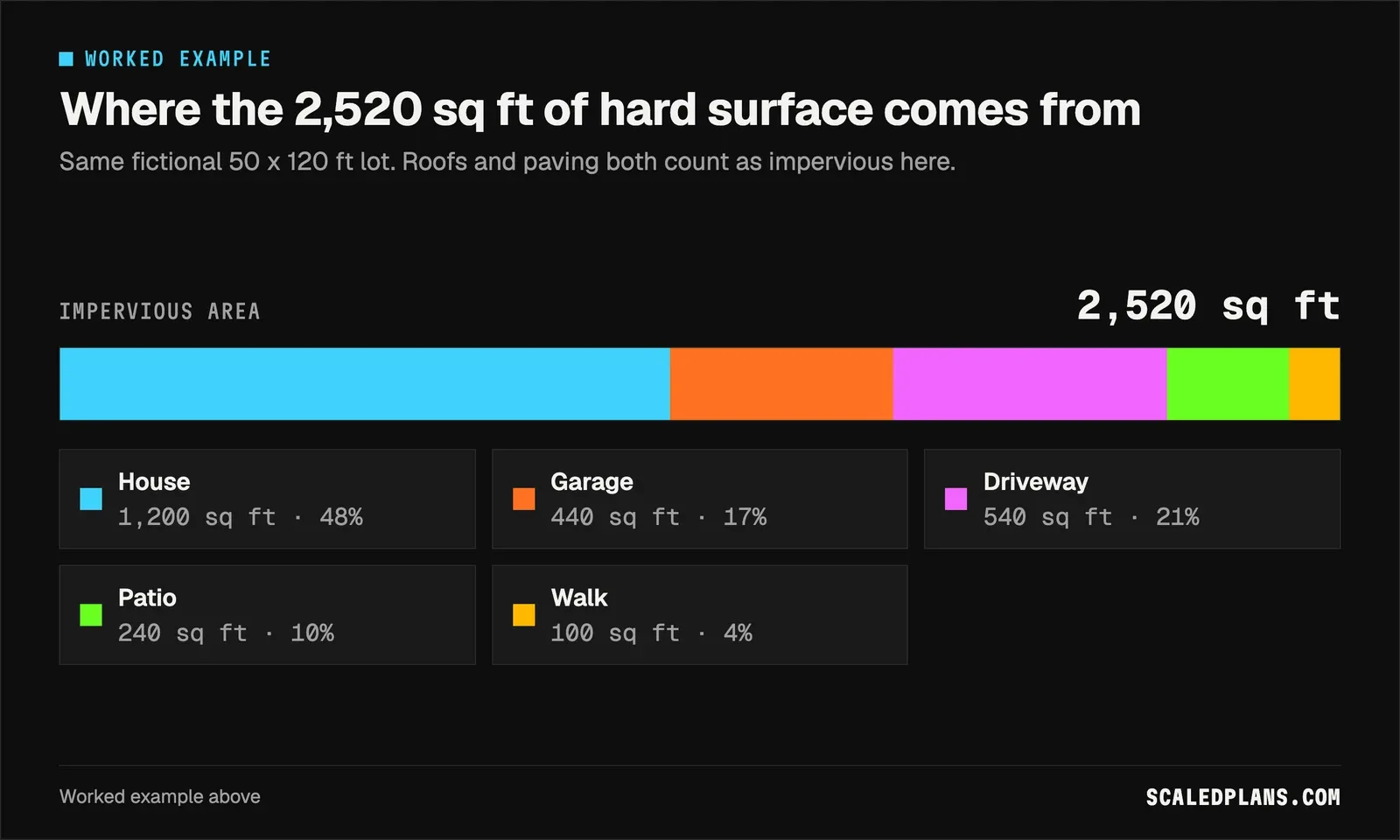
Two coverage numbers come out of the same five rectangles. Building coverage counts roofs only: 1,200 + 440 = 1,640 sq ft, or 27.3% of the lot. Impervious area adds the paving: 1,640 + 880 = 2,520 sq ft, or 42%.
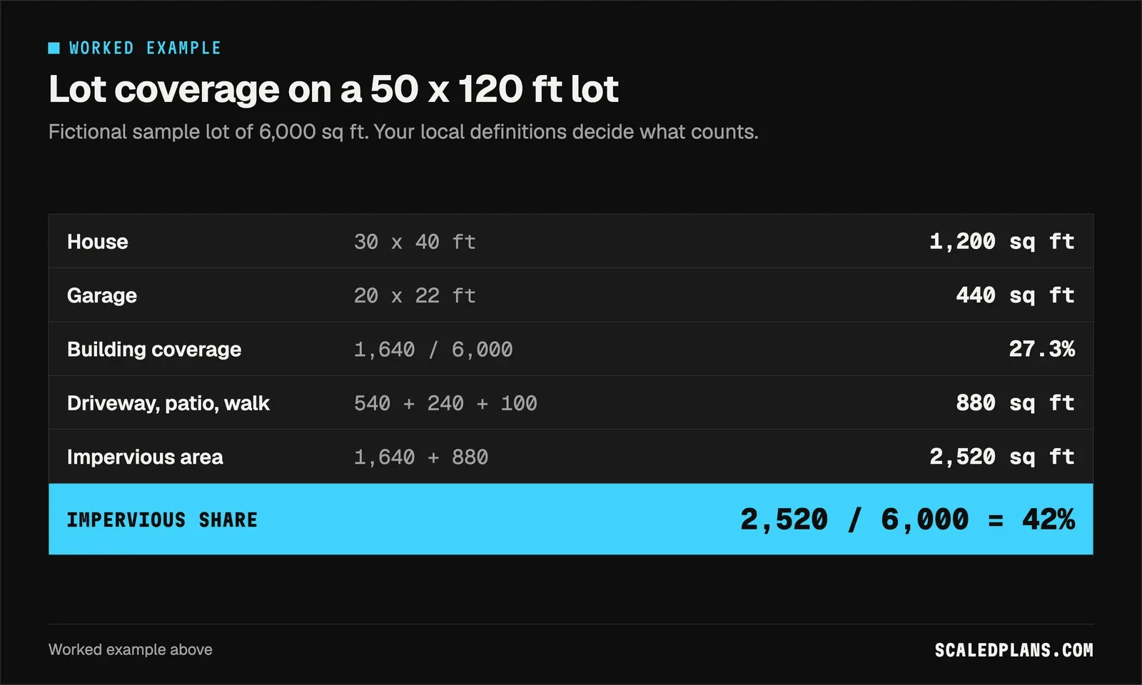
That second number is the one people forget. Many jurisdictions cap impervious surface separately from building coverage, because roofs and pavement shed water that would otherwise soak in. The EPA's page on urban runoff explains why streets and rooftops matter for drainage. Whether your patio counts, and what the cap is, depends on local definitions, so check with your permit office before you assume.
Look at where the hard surface comes from. The driveway alone is 540 sq ft, more than the 440 sq ft garage it serves. Add a 10 x 12 ft shed later and building coverage goes to 1,760 sq ft, or 29.3%, before you touch the house.
The same sheet also feeds your takeoff. The 30 x 40 ft house has a 140 ft perimeter (30 + 40 + 30 + 40), which is your starting length for exterior wall framing, foundation and siding.
How to draw a site plan
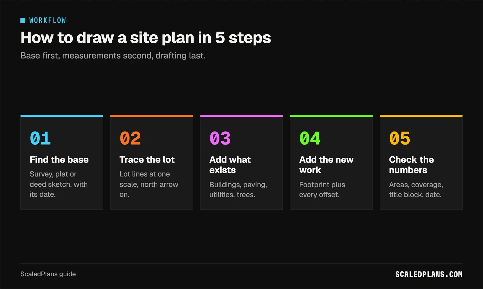
- Find the boundary record
Pull the survey or recorded plat from the closing documents or the county records office. Write its source and date on the sheet before you draw anything.
- Pick a scale and trace the lot
Choose a scale that fits the lot on the required sheet with room for notes. Draw the lot lines with their lengths, then add a north arrow and a scale bar.
- Add everything that exists
Draw the house, garage, sheds, decks, driveway, walks and patios as dimensioned outlines. Mark utility routes, meters and known easements with their source.
- Add the proposed work
Draw the new footprint with its dimensions and label it as proposed. Dimension the distance from it to every lot line it faces, starting from a clear corner.
- Check the numbers
Recompute footprint, building coverage and impervious area. Add a title block with the address, your name and a revision date.
Choosing a scale
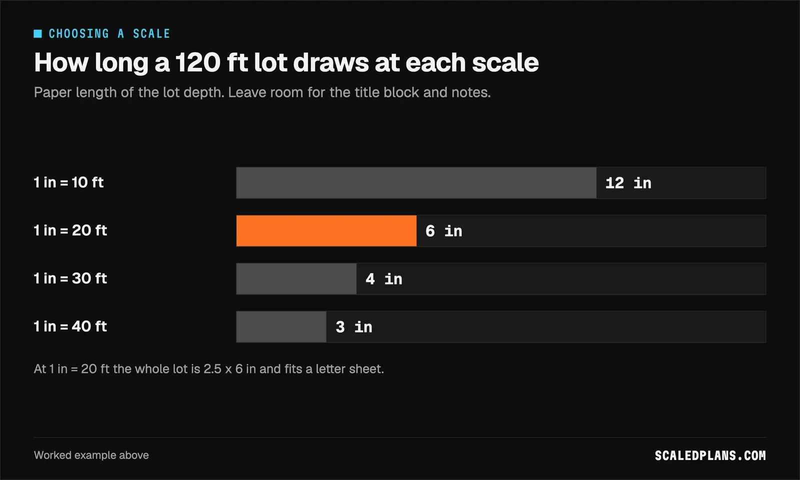
For the 120 ft deep sample lot, 1 in = 20 ft puts the whole lot on paper at 2.5 x 6 in. That fits a letter sheet with room for the title block. At 1 in = 10 ft the lot depth alone runs 12 in, so you need a larger sheet. Always draw a scale bar as well as writing the ratio: a bar stays true when the sheet is printed at a different size.
Which site plan do you need? It depends on the job
The core sheet stays the same. What changes is the detail each kind of project asks for and how much of the lot it touches.
| Your situation | What the site plan needs to show |
|---|---|
| Fence or shed | The run or footprint, gates, offsets to the nearest lot lines |
| Deck or patio | Footprint, stairs as their own outline, offsets, added hard surface |
| Addition or garage | New footprint, updated coverage, offsets on every new face |
| ADU or second building | Both buildings, access route, utility routes, coverage |
| Pool | Water outline, deck around it, barrier and gates, equipment |
| Bidding site work | Paving areas, trench routes and lengths, existing features to protect |
If you are filing for a permit, the site plan for permit guide walks through what reviewers check first and how to label offsets against setbacks. For an attached deck, the deck permit drawings walkthrough adds the framing plan and footing details that sit alongside the site sheet.
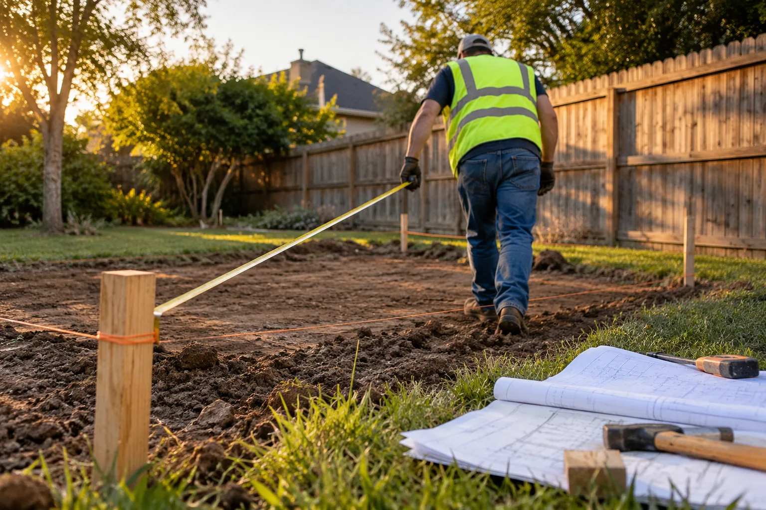
Drawing a site plan by hand, and where it stops working
You can do all of this with a survey copy, tracing paper, an architect scale and a pencil. For one fence or one shed, hand drawing is often the fastest route:
- Tape the survey under tracing paper and trace the lot lines at the survey's scale.
- Draw the existing buildings and paving from the survey or your own tape measurements.
- Draw the proposal and dimension every offset from a clear point.
- Compute the areas on a separate sheet and copy the totals onto the plan.
- Add the north arrow, scale bar, source note and date, then scan at the size the office wants.
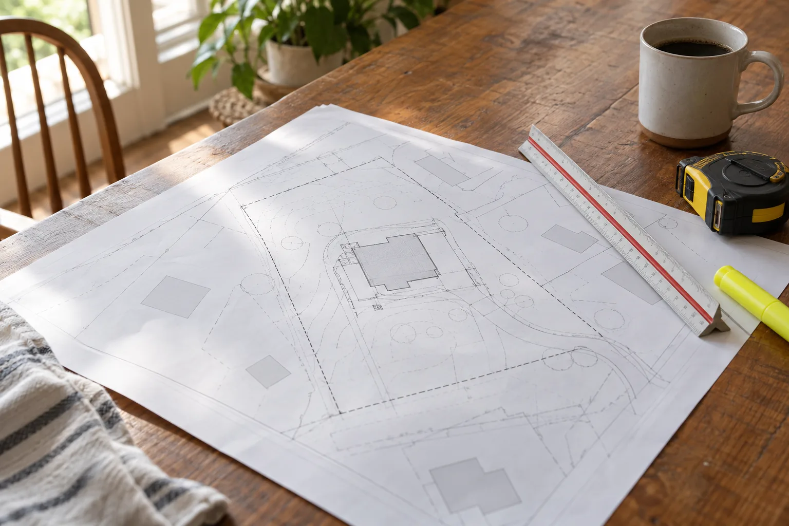
The wall shows up on revision two. The owner moves the garage 4 ft, the patio grows, and you are erasing offsets and redoing the coverage math by hand. The area totals on the sheet drift away from the quantities in your estimate. Nobody can tell which corner you measured from. And if the survey was a scanned PDF, every dimension you scale off it is a guess at the pixel.
Once the footprint settles, carry the same dimensions straight into your quantities. The 140 ft perimeter from the example is the input your framing count starts from, and the siding calculator uses the same wall lengths for cladding. The lumber takeoff guide shows how to turn that footprint into a full material list.
ScaledPlans measures the plan for you, and you check every quantity before you price it. Get started when the paperwork starts eating your evenings, or browse the free calculators first.
Common site plan mistakes
- Drawing on a parcel map screenshot. Online parcel maps are approximate. Use a survey or recorded plat and note its source and date.
- Counting only the buildings. Driveways, walks and patios often count toward impervious area. Compute both numbers.
- Writing a ratio without a scale bar. "1 in = 20 ft" breaks as soon as the sheet is resized. Draw the bar too.
- Leaving out utilities. A new footing over a sewer lateral is an expensive surprise. Mark known routes and call 811 before anyone digs.
- No revision date. Two versions of the same sheet with no date is how the wrong one gets built.
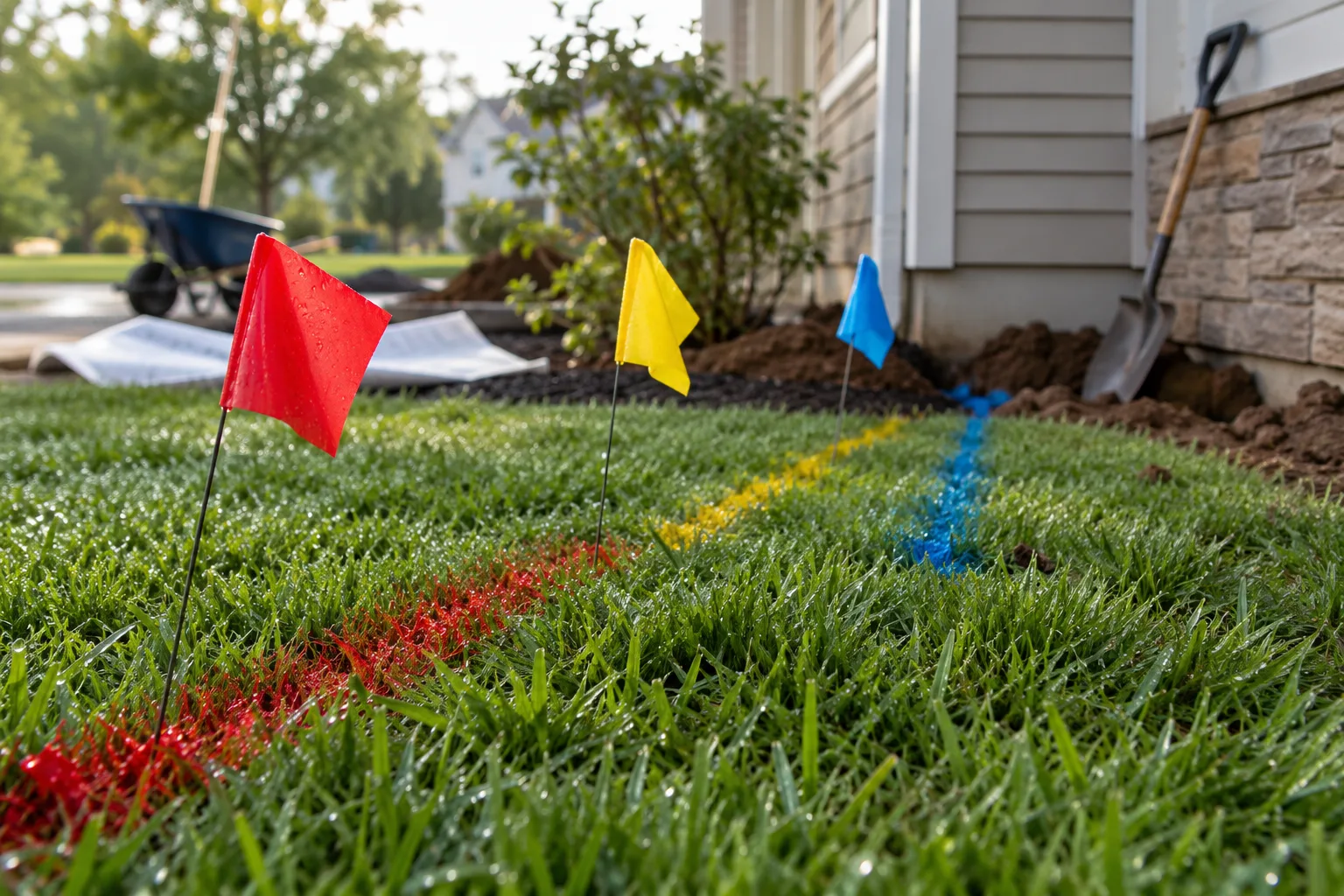
Before any excavation, the national 811 call before you dig service arranges for utility lines to be marked. Those marks show where lines actually run, which is often not where an old drawing puts them.
Who can draw up a site plan?
For most small residential projects, the property owner or the contractor can draw the site plan, as long as it sits on a boundary record the office accepts. Bigger projects, new homes and anything near a disputed or tight boundary often need a drafter, designer, architect, civil engineer or licensed surveyor. The reviewing office sets the rule for your application, so ask before you start.
A site plan is the drawing that puts every building and hard surface on the lot with measured distances and areas. The habit that matters most is working from a real boundary record and computing both coverage numbers, not drawing a prettier house. Draw your next one from the checklist above, then try the calculator or Get started when the quantities follow.
Frequently asked questions
Include the address, the boundary source and its date, lot lines with lengths, a north arrow and a scale bar. Show every existing building, driveway, walk and patio, then the proposed work with its dimensions and measured offsets to each lot line. Add utility routes, meters and known easements. Finish with footprint and coverage numbers and a revision date. Your permit office may add items for specific project types.
Sometimes. Some county or city building departments keep permit records and archived plans you can request, often through a public records request. The original builder, architect or a previous owner may also have copies. Online parcel maps give approximate lot outlines but not construction drawings. For older homes, plans often no longer exist, and you have to measure the building and draw it fresh.
A site management plan, often called a construction site management plan, describes how a job site is run during the build. It covers deliveries, storage areas, temporary fencing, dumpsters, parking, traffic control and erosion and sediment control. It is a logistics document, not a layout drawing, and it is usually required on larger projects. Check whether your jurisdiction or general contractor asks for one.
For simple residential work such as a fence, shed or deck, many offices accept a site plan drawn by the owner or contractor. New homes, additions near setback lines and projects with grading or drainage often need a drafter, architect, civil engineer or licensed surveyor. Only a licensed surveyor can establish legal boundary lines. Ask your permit office which qualifications it requires.
For most residential permits there is no real difference. Both show the lot, the buildings and the proposed work with offsets. Some jurisdictions use "site plan" for a larger review that adds grading, drainage, parking and stormwater, while "plot plan" stays the simple placement sheet. Use the term on your local checklist so the reviewer gets what they expect.
Start with your closing documents, which often include a survey or recorded plat. If not, ask the county recorder or the surveyor who prepared the original. The building department may also hold site plans from past permits on the house. If nothing exists, you can draw one on top of a new survey, or hire a surveyor when the boundary itself is uncertain.
Put it on your next bid
Plans in. Checked quantities out.
Upload the plan you are bidding, review every quantity on the drawing and export the list.
Share article
About the author
Founder
Oleh Onysko founded ScaledPlans and builds the product: how plans are measured, what each document includes and how every number stays checkable on the drawing.
More articles
 Permits & site plans · 10 min
 City of Houston permits: Prepare your residential packet
Start with the address and scope, then assemble a consistent residential permit packet. Includes a worked addition example and a review checklist.
 Permits & site plans · 12 min
 Garage Conversion Permit: 5 Steps and the Plans You Need
Turning a garage into a room or an ADU almost always needs a garage conversion permit. See what the permit office checks, what the plan set shows, a worked 400 sq ft example and why changing less gets you through faster.
 Permits & site plans · 13 min
 Site Plan for Permit: 9 Items Reviewers Check First
A site plan for permit shows your lot, existing buildings and the proposed work with measured offsets to each boundary. Here is what to include, a worked 60 x 100 ft deck example, and checklists for fences, pools, sheds, ADUs and solar.
 Permits & site plans · 13 min
 Deck Permit Drawings: 3 Sheets and a Worked 16x12 Deck
Deck permit drawings come down to three sheets: a site plan, a framing plan and connection details. This guide builds all three around one fictional 16 x 12 ft ledger deck, with every span, footing and guard number traced to a table you can open.