Single Line Diagram: How to Read and Draw One in 6 Steps
Oleh Onysko 16 October 2026 11 min read
In this article
A single line diagram (also called a one-line diagram or SLD) is a simplified electrical drawing that shows how power moves from the utility through the service equipment, panels and major loads, with one line standing for each circuit path. It tells you what connects to what; the panel schedule tells you what each circuit serves, and the floor plan tells you where everything sits.
Here is the part most people get backwards: a one-line with its blanks marked "unresolved" is more useful than one that looks finished. Fill a missing rating with a typical value and the sheet looks done, but nobody reviewing it can tell a verified nameplate from a guess. Keep the gap visible until someone closes it with evidence.
| Item | Answer |
|---|---|
| What it shows | Supply, service, panels, major loads and how they connect |
| What one line means | A circuit relationship, not a wire count or a route |
| Read it with | Panel schedule, equipment register, nameplates |
| Typical residential tags | UT1 utility, SE1 service, P1 panel, PV1 inverter |
| Rules that govern it | The NEC edition your jurisdiction adopted, plus utility rules |
| What it does not prove | Spare capacity, conductor size or connection approval |
What a single line diagram shows
A single line diagram compresses a power system into one readable path. Each drawn line is a relationship between two pieces of equipment, not the physical conductors. A 240 V feeder with two hots, a neutral and a ground still gets one line. Equipment symbols and tags identify the source, the disconnecting means, the distribution and the big loads.
Read the legend first. The same-looking mark can mean a different thing in a different drawing set, and a symbol with no tag, rating or note tells you only part of the story. Then start at the supply and follow each connection to where it ends.
On a residential job, label existing equipment and new equipment in words or in the legend. Do not rely on color: it disappears on a black and white print, which is exactly what ends up on the inspector's clipboard. Where the service configuration is unknown, write "unknown" in the field. A blank that says what is missing is a task; a guessed rating is a trap.

The diagram is an index into the rest of the electrical record. Every significant tag should lead you to a schedule, a nameplate photo or a spec sheet. If a tag leads nowhere, that is the first open item on your list.
One line diagram vs three line diagram vs panel schedule
These documents answer different questions, so a permit set often needs more than one. Keep the questions apart and a small addition stays easy to coordinate, even when it changes only part of an existing house.
| Document | Answers | Example question |
|---|---|---|
| One-line | What connects to what | Does PV1 tie into P1 or SE1? |
| Three-line | Each phase conductor drawn | How are L1, L2 and N landed? |
| Wiring diagram | Terminal by terminal hookup | Which terminal takes which wire? |
| Panel schedule | What each circuit serves | Is circuit 14 the range? |
| Floor plan | Where devices sit | Where is the outdoor disconnect? |
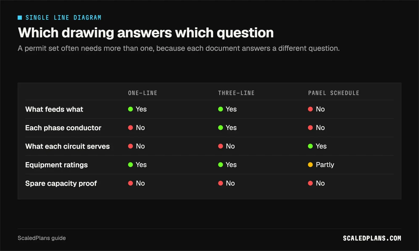
P1 has to mean the same panel on the drawing, the schedule and the equipment list. If you are adding load, run a separate demand worksheet with the electrical load calculator and keep its inputs, code edition and scope beside the schedule. Never add up breaker handle ratings and call the sum service demand. An empty breaker space is not proof that the service can take another big appliance.
Worked example: four tags, one closed, three open
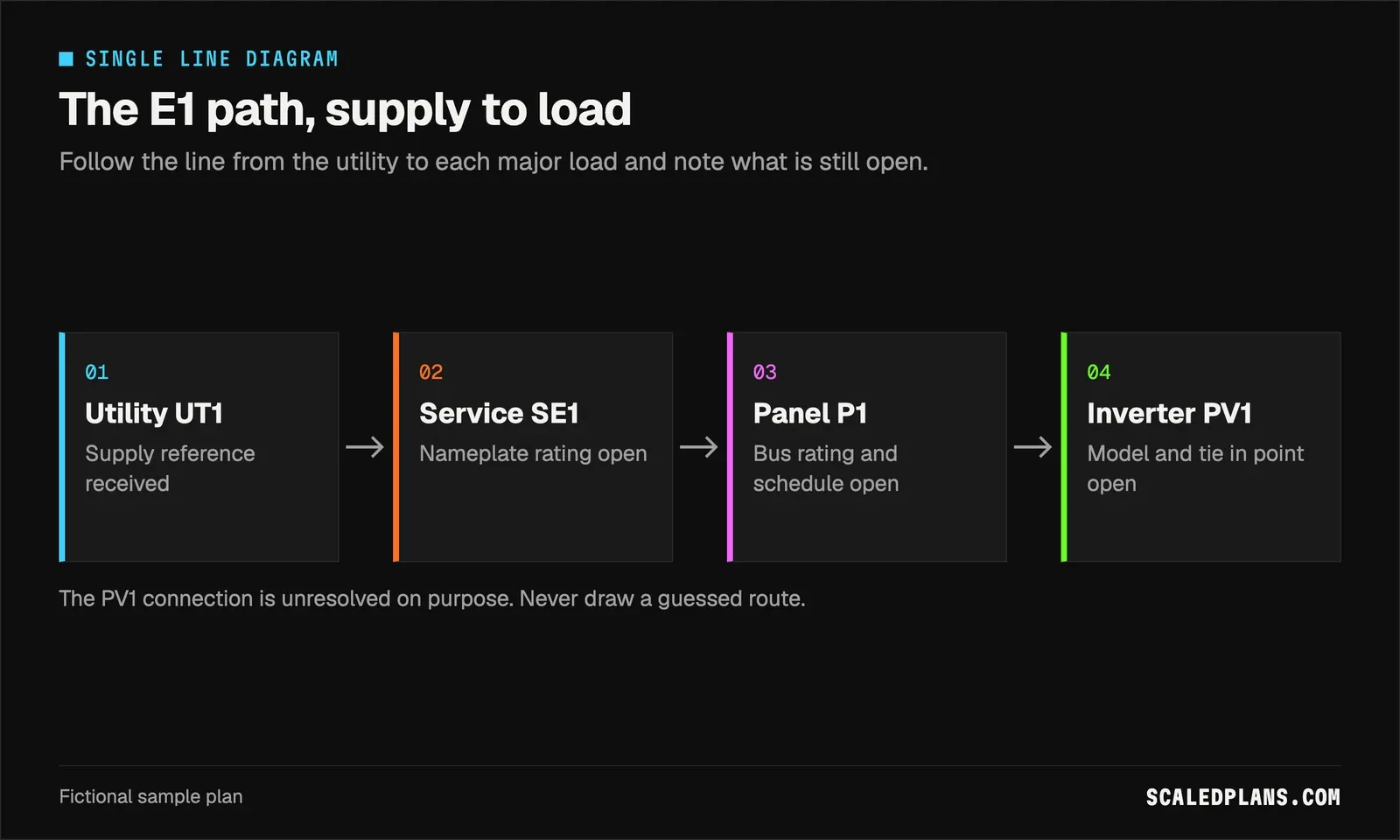
Take a fictional sample sheet, E1, with four equipment references: UT1 utility, SE1 service equipment, P1 distribution panel and PV1 inverter. The ratings are missing on purpose, and the solar connection point is marked unresolved. This is a document review exercise, not a design.
Say the utility identification comes in first. You can close one of four register rows. That leaves three to chase, and each one needs different evidence.
| Tag | Information to reconcile | Status |
|---|---|---|
| UT1 | Utility supply reference | Received: 1 row closed |
| SE1 | Service nameplate and rating | Open |
| P1 | Panel bus rating and circuit schedule | Open |
| PV1 | Inverter model and reviewed connection | Open |
| Register | 4 references minus 1 closed | 3 follow-up rows |
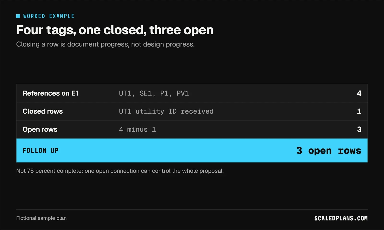
Do the math honestly: 4 minus 1 is 3 open rows. It is not "75 percent complete." Counting closed rows helps you coordinate documents, but it says nothing about technical completeness, because one unresolved connection, like PV1, can control the whole proposal. Carry the open status into the next issue instead of drawing a guessed route to make the page look finished.
How to make a single line diagram for a residential job
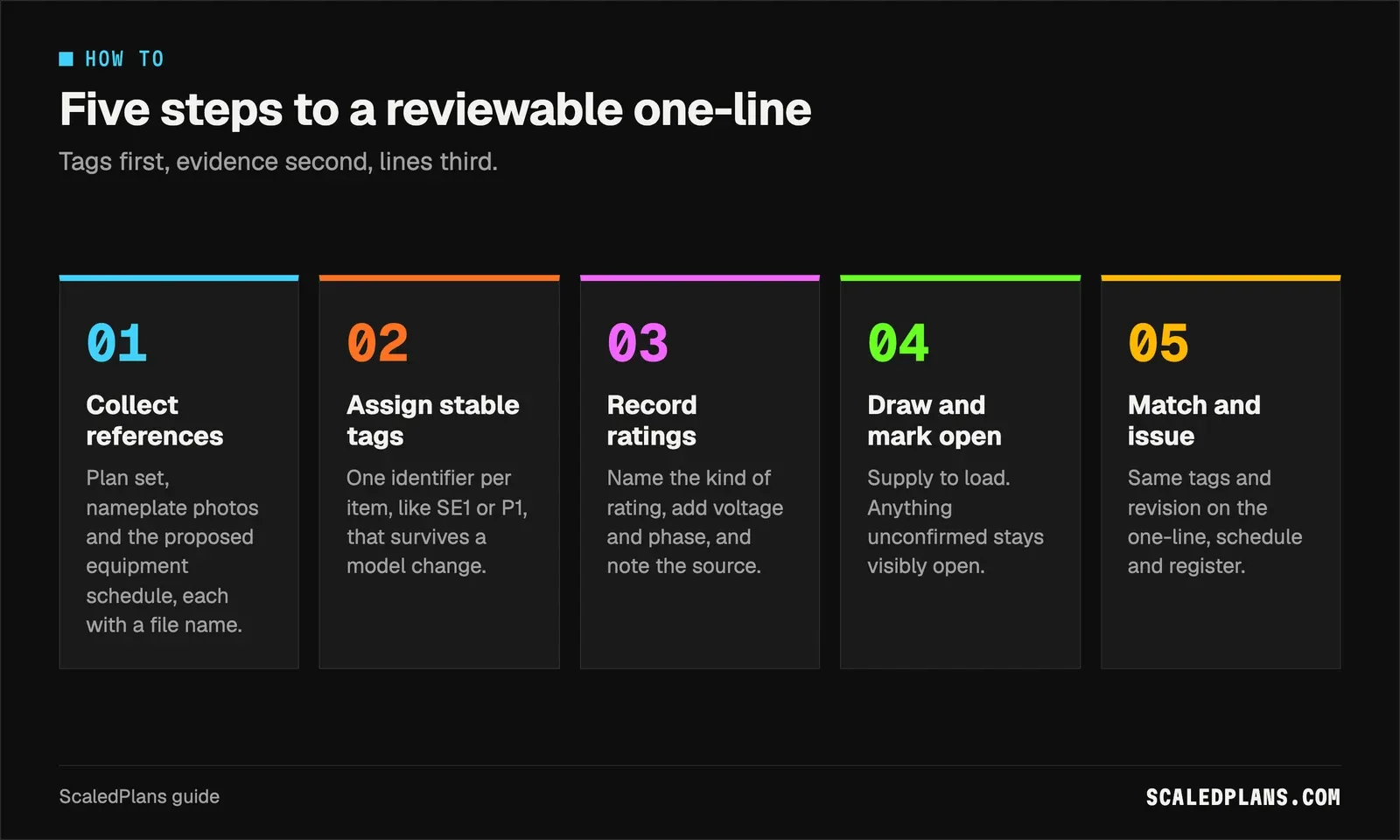
- Collect the references
Bring the current plan set, readable nameplate photos and the proposed equipment schedule. Give each photo and data sheet a file name so a reviewer can see the evidence behind every tag.
- Assign stable tags
Give every major item one identifier, like SE1 or P1, before you draw final lines. A tag should survive a model change so the revision history still makes sense.
- Record ratings with their source
Write the kind of rating next to the number: bus rating, breaker rating or connected load. Add voltage and phase. A bare amp value loses its meaning once it is copied into another document.
- Draw the connections from supply to load
Start at the utility, go through the service and panels, and end at the major loads. Leave any connection you cannot confirm marked as open.
- Add the legend, revision and open items
Note existing versus new in words, date the issue and attach the open items list to the sheet, not to someone's text messages.
- Match the panel schedule and issue
Check that every tag on the one-line matches the schedule and register, then issue all three with the same revision reference.
Solar, service upgrades and additions: what to check
The situation decides what the one-line has to carry. Use this as a starting checklist, then confirm what your permit office and utility want submitted.
| Situation | What to check |
|---|---|
| Adding rooftop solar | Inverter model verified; leave the tie-in point open until the designer and utility decide |
| Service upgrade | SE1 nameplate, bus rating and utility requirements; show old and new |
| Adding a heat pump or EV charger | Nameplate electrical input, a separate demand calc and a P1 schedule entry |
| Panel swap only | Same P1 tag on drawing, schedule and register, plus a revision note |
| Addition with outdoor equipment | Tags match the site plan; one-line length is not a raceway length |
Solar adds the most fields. The Department of Energy's rooftop solar permitting resources show how much of a solar review rides on the electrical documents, and the rules still vary by jurisdiction and utility.
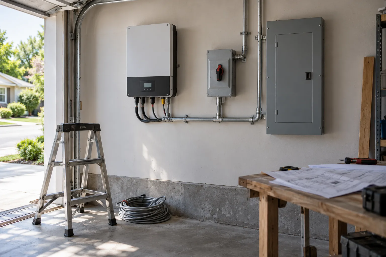
Outdoor equipment also lives on the site plan for permit, and the tags should agree across both sheets. Do not scale a one-line connection as if it were an installed conduit run; for real lengths and device counts, see how electrical estimating software handles routes. And for a new heat pump, the cooling number from a Manual J calculation is in Btu/h, a thermal unit. It cannot be dropped into a VA column. Use the selected unit's electrical nameplate.
Drawing a one-line by hand, and where it breaks
You can do all of this on paper or in a basic CAD file. Draw the path, keep a register spreadsheet with two columns for each source, "received" and "verified," and fill a free panel schedule template for each panel. A clear photo can satisfy "received" without satisfying "verified": a qualified person still has to confirm it shows the equipment that serves the work. Other worksheets for the same job live in the construction tools hub.

The hand method holds up for one issue. It breaks at the second revision. You re-trace the sheet, renamed loads turn into duplicate schedule rows, the nameplate photos sit in a phone, and nobody can say which items were checked on which date.
ScaledPlans measures the plan and builds the quantities with you, and you check every quantity before you price it. Get started with your current plan set.

Common single line diagram mistakes
- Adding breaker handles and calling it demand. Run a demand calculation with a stated method and keep it separate from the schedule.
- Filling blanks with typical ratings. Write "unknown" and add the item to the open list with an owner.
- Using color alone for existing vs new. Label it in words or in the legend so it survives a print.
- Scaling the schematic line as a route. Measure installed lengths on the floor plan or site plan, never on the one-line.
- One tag, two meanings. Check that every tag means exactly one thing across drawing, schedule and register.
What is an SLD drawing used for?
An SLD is used to review how a system is fed and protected without reading every wire. On a home job it supports service upgrades, solar and battery permits, panel replacements and utility applications. It is also the quickest way for a new electrician on the job to see the whole system.
Does a single line diagram show spare capacity?
No. A one-line shows relationships, and the panel schedule shows connected circuits. Neither proves capacity by itself. Capacity comes from a demand calculation under the method your adopted NFPA 70 (NEC) edition allows, checked by a licensed electrician.
A single line diagram is the map of how power reaches your equipment: supply, service, panels and big loads on one readable path. The habit that matters most is keeping every tag tied to evidence and every unknown visibly open. Fill the free panel schedule template next to your one-line, or get started with ScaledPlans when the revisions start piling up.
Frequently asked questions
A one-line diagram is the same thing as a single line diagram: a simplified electrical drawing where one line represents each circuit path between pieces of equipment. It shows the utility supply, service equipment, panels, disconnects and major loads, with tags and ratings. It is built for reading the system at a glance, so it leaves out individual conductors, terminal connections and physical routing. Those details live on three-line diagrams, wiring diagrams and floor plans.
A three-line diagram draws each phase conductor separately instead of combining them into one line. That gives conductor-level detail, such as how each leg and the neutral land, which helps with metering, transfer switches and some solar or battery reviews. It still needs its legend and project notes. More lines do not make a sheet more complete; choose the drawing type your designer and reviewer actually ask for.
Start with the utility supply and list every major piece of equipment. Give each one a stable tag, then record verified ratings next to the tag with their source. Draw the connections from supply to loads, mark anything unconfirmed as open, and add a legend, date and revision number. Finally, match every tag against the panel schedule and resolve design questions with the responsible professional before submission.
A single line diagram is a type of schematic focused on power distribution at the system level. A general wiring schematic shows how individual devices and terminals connect, often wire by wire. The one-line answers what feeds what and how it is protected. The wiring schematic answers how to physically hook it up. Most residential permit sets that need one will ask for the one-line, not the detailed schematic.
SLD stands for single line diagram, sometimes written single-line diagram or one-line diagram. All three names describe the same drawing. You will see SLD on solar and battery permit checklists, utility interconnection applications and service upgrade packages. When a checklist asks for an SLD, it usually wants equipment tags, ratings, the point of connection and the disconnecting means shown clearly.
Read the legend first so you know what each symbol means in that set. Then start at the utility supply and follow the line through the meter, the service disconnect and each panel to the major loads. At every symbol, check the tag, the rating and any note. Write down every tag that has no matching schedule, nameplate or spec sheet, because those are the open items to close before review.
Put it on your next bid
Plans in. Checked quantities out.
Upload the plan you are bidding, review every quantity on the drawing and export the list. Or start with the free electrical load calculator.
Share article
About the author
Founder
Oleh Onysko founded ScaledPlans and builds the product: how plans are measured, what each document includes and how every number stays checkable on the drawing.